1-26
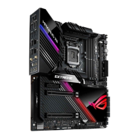
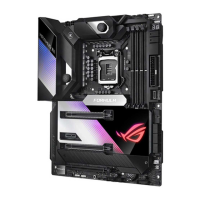
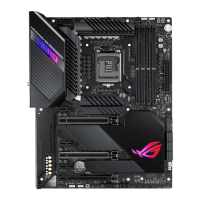
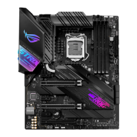
Chapter 1: Product Introduction
Chapter 1
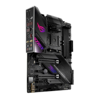
14. System panel connectors (10-1 pin F_PANEL)
Theseconnectorssupportsseveralchassis-mountedfunctions.
• SystempowerLED(2-pinPLED)
This2-pinconnectorisforthesystempowerLED.ConnectthechassispowerLED
cabletothisconnector.ThesystempowerLEDlightsupwhenyouturnonthesystem
power,andblinkswhenthesystemisinsleepmode.
• HarddiskdriveactivityLED(2-pinHDD_LED)
This2-pinconnectorisfortheHDDActivityLED.ConnecttheHDDActivityLEDcable
tothisconnector.TheHDDLEDlightsuporasheswhendataisreadfromorwritten
totheHDD.
• ATXpowerbutton/soft-offbutton(2-pinPWRBTN)
Thisconnectorisforthesystempowerbutton.Pressingthepowerbuttonturns
thesystemonorputsthesysteminsleeporsoft-offmodedependingontheBIOS
settings.PressingthepowerbuttonformorethanfoursecondswhilethesystemisON
turnsthesystemOFF.
• Resetbutton(2-pinRESET)
This 2-pin connector is for the chassis-mounted reset button for system reboot without
turning off the system power.
 Loading...