3-6
Chapter 3: Motherboard info
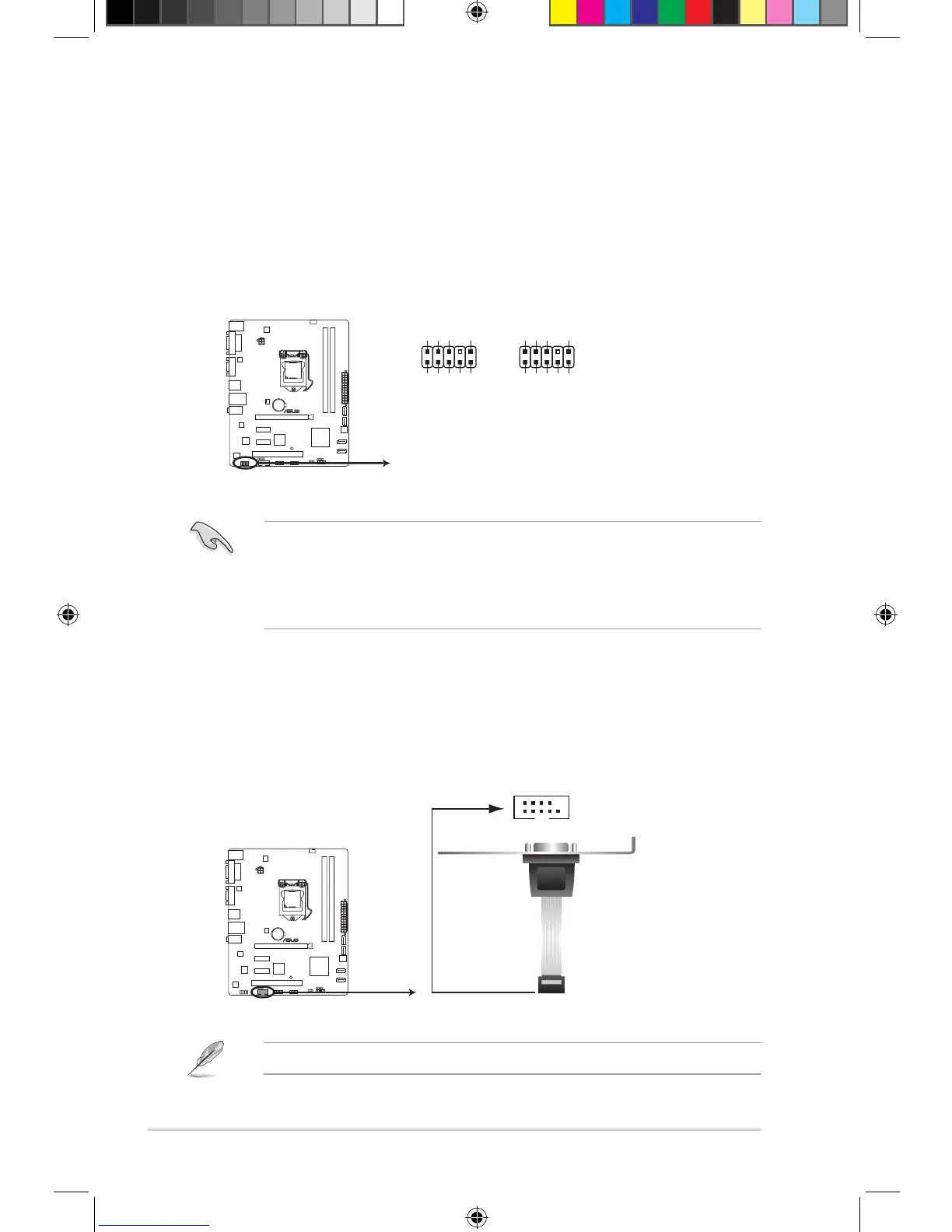
5. Front panel audio connector (10-1 pin AAFP)
This connector is for a chassis-mounted front panel audio I/O module that supports either
HD Audio or legacy AC’97 audio standard.
• We recommend that you connect a high-denition front panel audio module to this
connector to avail of the motherboard’s high-denition audio capability.
• By default, this connector is set to HD Audio. If you want to connect a High Denition
front panel audio module to this connector, set the HD Audio Controller item in the
BIOS to [Enabled]. See section “4.4.6 Onboard Devices Conguration” for details.
6. Serial port connector (10-1 pin COM1)
This connector is for a serial (COM) port. Connect the serial port module cable to this
connector, then install the module to a slot opening at the back of the system chassis.
The COM module is purchased separately.
 Loading...