Disassembly Procedure
23
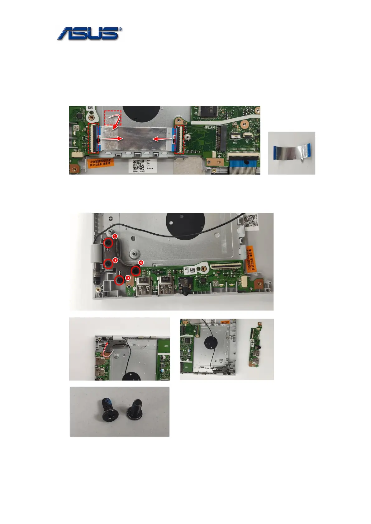
IO Board Module
The illustrations below show how to remove the IO Board Module.
1. Disconnect the IO FFC.
Assembly notice: Insert FFC to the bottom until just accord with the line when lock the latch.
2. Remove 4 screws and take out the IO Board.
Assembly Notice: follow the reverse numbers to lock screws.
Screw tightening torque: 2.5KG±0.2kgf
SCREW M2.5*5.5L(4.5,0.8) (K)#1
 Loading...