1-4
Chapter 1: Product introduction
12. COM Port headers
These headers are for serial (COM) ports. Connect the serial port module
cablestotheseheaders,theninstallthemodulestoslotopeningsattheback
of the system chassis.
13. Front panel audio header
Thisheaderisforachassis-mountedfrontpanelaudioI/Omodulethat
supports HD audio standard. Connect one end of the front panel audio
I/Omodulecabletothisheader.
• Werecommendthatyouconnectahigh-denitionfrontpanel
audiomoduletothisheadertoavailofthemotherboard’shigh-
denitionaudiocapability.
• Ifyouwanttoconnectahigh-denitionfrontpanelaudio
moduletothisheader,settheFrontPanelTypeiteminthe
BIOSsetupto[HDAudio].Bydefault,thisheaderissetto[HD
Audio].
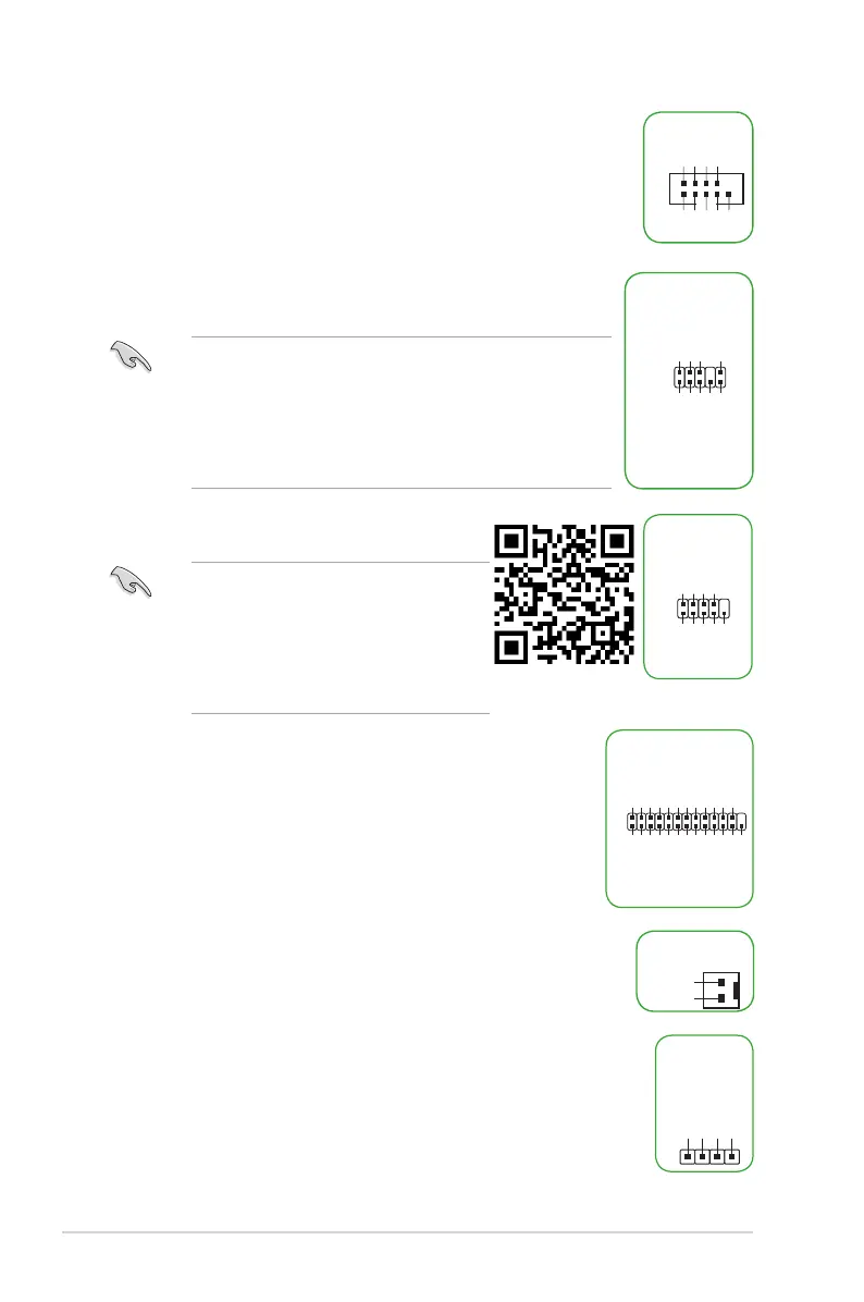
14. LPC Debug header
ThisheaderallowsconnectiontoaLPCDebugcard.
• ScantheQRcodetoviewthemeaningof
each debugging code.
• Debuggingcodesareonlyavailablefor
ASUSLPCDebugcards.
• Contactyourregionsalesrepresentative
forLPCDebugcardsordering.
15. LPT header
TheLPT(LinePrintingTerminal)headersupportsdevicessuchas
aprinter.LPTstandardizesasIEEE1284,whichistheparallelport
interfaceonIBMPC-compatiblecomputers.
16. Mono-out header
ThisinternalMono-outheaderallowsconnectiontoaninternal,lowpower
speaker for basic system sound capability. The subsystem is capable of
drivingaspeakerloadof3WattsRMSat4Ohms.
17. Speaker header
The 4-pin header is for the chassis-mounted system warning speaker. The
speaker allows you to hear system beeps and warnings.
AAFP
AGND
NC
SENSE1_RETUR
SENSE2_RETUR
PORT1 L
PORT1 R
PORT2 R
SENSE_SEND
PORT2 L
HD-audio-compliant
pin definition
PIN 1
COM
DCD
TXD
GND
RTS
RI
RXD
DTR
DSR
CTS
PIN 1
O_LPT_XSTB#_R
O_LPT_XPD0_R
O_LPT_XPD1_R
O_LPT_XPD2_R
O_LPT_XPD3_R
O_LPT_XPD4_R
O_LPT_XPD5_R
O_LPT_XPD6_R
O_LPT_XPD7_R
O_LPT_ACK#_R
O_LPT_BUSY_R
O_LPT_PE_R
O_LPT_SLCT_R
O_LPT_XAFD#_R
O_LPT_ERROR#_R
O_LPT_XINIT#_R
O_LPT_XSLIN#_R
GND
GND
GND
GND
GND
GND
GND
GND
PIN 1
+3V
+3V
CK_24M_LPC
GND
S_LAD0
S_LAD1
S_LAD2
S_LAD3
S_LFRAME#
LPC_DEBUG
R_OUT-
R_OUT+
PIN 1
MONO-OUT
+5V
GND
GND
Speaker Out
SPEAKER
PIN 1