12
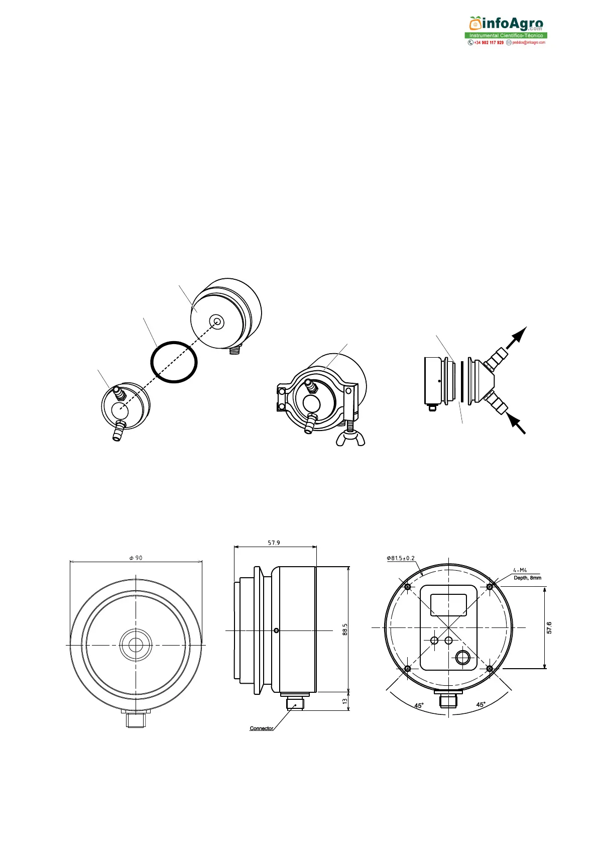
Mounting procedure (Fig. 6-1, Fig. 6-2, and Fig. 6-3)
① Install the CM-BASEα so that the prism surface is at a right angle to the ground.
② Attach the sample inlet unit to the CM-BASEα with O-ring inserted between them, and
fasten them together with the clamp band.
③ Install the inlet unit so that the sample solution runs from the lower nozzle to the upper
nozzle to prevent air bubbles from forming.
④ When connecting the tubes to the hose connector, clamp them with a tie band. The tie
bands provided with the hose connector are made of plastic. If chemicals corrosive to
plastics are used, substitute with tie bands made of other material.
⑤ The prism surface may become contaminated with solids, dirt and/or grease. If this
happens, the prism surface must be cleaned by hand. (See page 22.) The sample
inlet unit should be installed in such a manner that it can be easily removed to allow
access to the prism for cleaning.
Dimensions
Sample inlet
unit
(optional)
ex.hose connector