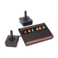
2. Remove the upper RF shield by using your needle nose pliers to twist the hold down metal tabs and make them
stand straight up and flat so they will fit through the slots they originally come up from.
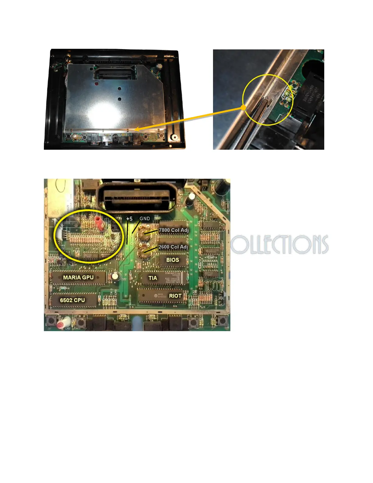
3. Locate the area where wires will be attached on the resistor ladder section just to the right and below the RF
modulator area. The area circled in yellow is the resistor section for video taps.
4. Decide where you want to mount the MK AV board inside the system. A good place is on top of the RAM chips
above the BIOS rom. Avoid placing it on the 6502 CPU or Maria as they get hot.
5. Measure out the lengths of wire you will need for connections from the MK AV board to the resistor section and
also from the MK AV board to where you decide to place your AV out jacks. 14 total connections will be made to
the MK AV board.
©2019 – Cro§Bow - Ivory Tower Collections