Do you have a question about the Atdec AWM-A71-B and is the answer not in the manual?
The Atdec AWM-A71 is a 710 Arm designed for monitor mounting, offering flexibility and adjustability for various display setups. This installation guide outlines the process of assembling and configuring the arm, along with important technical specifications and usage features.
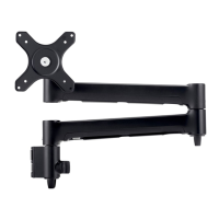
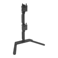
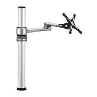
The AWM-A71 monitor arm is designed to securely hold flat or curved monitors, providing ergonomic positioning and efficient workspace management. It attaches to a post or wall channel, allowing users to adjust the monitor's height, tilt, and rotation. The arm's modular design is compatible with other Atdec AWM Series products, enabling a customizable monitor mounting solution. Key components include the monitor arm itself, a VESA head for monitor attachment, a post clamp for securing the arm to a channel, and various screws and tools for assembly.
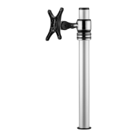
The post clamp (C) is designed to slide into a post or wall channel. To install, ensure the knob on the clamp is undone, then slide the clamp into the channel. Push the knob to aid insertion. Once in the desired position, turn the knob to lock the clamp securely in place.
By default, the arm rotation is set to 360°. To change this to 180°, first remove the plastic sleeve from the post clamp. Then, remove the rotation ring. The rotation ring can be placed in two positions: "Default Position" (360°) or "180° Flipped Position." The tag on the rotation ring should always face the user. To adjust, lift the arm, press, and then place the rotation ring in the desired position.
Once the post clamp is secured and the rotation is set (if adjusted), push the monitor arm (A) onto the shaft of the post clamp. Ensure the arm is fully pushed onto the shaft. Finally, tighten the joint screw to secure the arm. After tightening, check that the arm rotation is smooth.
The VESA head (B) is screwed onto the back of the monitor. Select the appropriate screw length (D, E, or F) based on the monitor's depth. Screws come in 5mm (flush) and 12mm (spacer) lengths. Spacers (G) may be required for curved, recessed, or uneven monitor surfaces to ensure a proper fit. Avoid using screws that are too long (which can damage the monitor) or too short (which won't secure the monitor properly).
With the VESA head attached to the monitor, insert the VESA head into the monitor arm. Ensure that the VESA head sits flush within the monitor arm, with no gap. To secure the monitor to the arm assembly, push the lever down.
The tilt tension of the monitor can be adjusted using the 4mm allen key (I). Adjust the tension until the monitor holds a vertical position at the end of the arm. It's important to support the monitor while adjusting. An optional security screw (H) can be installed by tilting the head upwards and screwing it in, providing additional security.
The monitor arm includes cable hooks and clips for organizing cables. Plug cables into the monitor and route them down the arm using these integrated features to maintain a tidy workspace and prevent cable tangles. Ensure enough cable slack is provided to allow for full movement of the monitor without strain.
For managing cables along the post, push the cable down into the cable clip. Then, push the cable clip into the post channel. Note that cable clips do not come with all posts. For double or triple arm setups, a recommended post cable cover position involves using a "Desk Clamp" and "Cable Cover." To reposition the cable cover, pull it straight up and out of the post and insert it into any of the available channels. Note that the cable cover shown does not come with all posts. For additional cable management, loop excess cable and insert it into the cable cover, then feed any remaining cable into the cover.
The Atdec AWM-A71 is designed for durability and ease of use, providing a robust solution for ergonomic monitor placement. Its modularity allows for integration with other Atdec AWM Series products, offering a flexible and scalable mounting system. Regular checks of screw tightness and cable management are recommended to ensure continued optimal performance and safety.
| Brand | Atdec |
|---|---|
| Model | AWM-A71-B |
| Category | Racks & Stands |
| Language | English |