Do you have a question about the Atdec TH-1040-CTS and is the answer not in the manual?
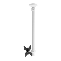
The ATDEC 1040 Ceiling Mount is a versatile mounting solution designed to securely suspend displays from ceilings, offering a range of configurations to suit various installation needs. This product is engineered for professional installation and is intended for indoor use, providing a robust and adaptable platform for display integration in commercial or residential environments.
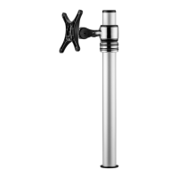
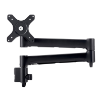
The primary function of the ATDEC 1040 Ceiling Mount is to provide a stable and adjustable overhead mounting point for displays. It consists of a ceiling mounting plate, a pole assembly, and a VESA plate that attaches to the display. The system allows for precise positioning of the display, including height adjustment, tilt, pan, and rotation, ensuring optimal viewing angles. The modular design supports various configurations, including single displays, back-to-back displays, and double vertical setups, catering to diverse display requirements.
The ATDEC 1040 Ceiling Mount offers a comprehensive set of features designed for ease of use, flexibility, and secure display management:
The ATDEC 1040 Ceiling Mount is designed for durability and minimal maintenance, with key features facilitating long-term performance:
In summary, the ATDEC 1040 Ceiling Mount is a robust, highly adjustable, and professionally installed display mounting solution that prioritizes secure attachment, flexible positioning, and a clean aesthetic for a wide range of indoor applications.
| Tilt angle range | -20 - 20 ° |
|---|---|
| Ceiling mounting tube length (max) | 90 cm |
| Ceiling mounting tube length (min) | 40 cm |
| Mounting type | Ceiling |
| Maximum VESA mount | 100 x 100 mm |
| Minimum VESA mount | 75 x 75 mm |
| Maximum weight capacity | 25 kg |
| Product color | Black |