Do you have a question about the Atdec AWMS-2-BT75 and is the answer not in the manual?
Specifies the Phillips Head Screwdriver as the required tool for assembly.
Details weight capacity for flat/curved monitors and maximum display depth.
Attach post to upper clamp using M8x60mm screws and 5mm hex key.
Measure worksurface thickness and select the appropriate lower clamp position.
Attach lower clamp to upper clamp using M8x16mm screws and 5mm hex key.
Place clamp on worksurface and tighten pressure plates evenly and firmly.
Remove clips and covers from the post by sliding them up or squeezing sides.
Ensure VESA compatibility and attach VESA plate using screws or spacers.
Attach bracket with display facing front, slide into channel, and tighten.
Set VESA plate clips to open position; bottom display attaches first.
Lift display, align VESA plate bar into bracket saddle, and close clips.
Adjust display tilt by gripping screen edges; ensure clips are closed before tilting.
Use hex key to adjust tilt friction for screen weight (clockwise increases friction).
Ensure bracket spacing is sufficient for display height; top monitor must hang freely.
Repeat steps 5 and 6 to attach the top display and set its tilt angle.
Adjust horizontal screen angle using a single fine-tune knob.
Close gap between displays using both fine-tune knobs, alternating sides.
Load cables into cable clips and cover, then secure cover onto post channels.
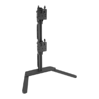
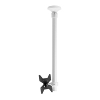
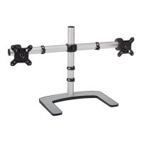
The ATDEC Post Mounted Heavy Duty Dual Vertical Monitor Mount, model AWMS-2-BT75-H, is a robust solution designed for securely mounting two monitors in a vertical configuration. This system is engineered to provide a stable and adjustable platform for displays, enhancing ergonomic setups in various work environments. The core function of this device is to elevate and position monitors, freeing up desk space and allowing users to customize their viewing angles for optimal comfort and productivity.
The installation process begins with assembling the post to the clamp. This involves attaching the post to the upper clamp using M8x60mm screws and a 5mm hex key. A crucial step is to measure the worksurface thickness to determine the appropriate lower clamp position, ensuring a secure fit. The lower clamp is then attached to the upper clamp using M8x16mm screws and a 5mm hex key. If there's limited space behind the worksurface, it's advised to perform the initial clamp fitting before placing it on the desk. Once the clamp assembly is complete, it is placed in the desired location on the worksurface, and both pressure plates are screwed in evenly and firmly to secure the mount. Clips and covers are then removed from the post by sliding them up and out or by squeezing their sides, preparing the post for bracket attachment.
Attaching VESA plates to the displays is the next step. The manual outlines two options for this. Option A involves attaching the VESA plate directly to the monitor using M4x10mm screws. Option B is for recessed VESA mounts, requiring the use of 10mm spacers and M4x20mm screws to ensure proper clearance and fit. For 75mm VESA patterns, a 5mm screw needs to be unscrewed to access the top holes. It's important to note that some displays may require a separate VESA adapter, which might be included with the display itself; users should consult their display's installation guide for such cases.
Once the VESA plates are secured to the monitors, the brackets are slid onto the post and their height is set. The tilt bracket must be attached with the display facing the front of the mounting surface. The inner guide on the rear of the bracket is aligned with the rear channel on the post, then slid into the channel, and the bracket is lowered. The hand knob is then firmly tightened at the chosen height, ensuring sufficient clearance for the display once it's in place. This process is repeated for the second bracket, and the post cap is fitted. A critical warning is issued: never loosen the knob while a display is on the bracket, as this could lead to instability.
Attaching the bottom display is a two-person task for safety. First, the VESA plate clips are set to the open position. The display is then lifted until the VESA plate is above the bracket. The VESA plate is centered close to the post and slowly lowered until the bar on the VESA plate sits securely in the saddle of the bracket. Finally, the VESA plate clips are set to the closed position. The manual clarifies that the display will hang from the bracket like a painting, and some rocking movement is expected if the corners of the screen are pushed downwards after the clips are closed. Another warning emphasizes not to loosen the hand knob with the display attached.
Setting the tilt for the display involves gripping the edges of the screen and rolling it up or down to achieve the desired angle. Before tilting, it's crucial to ensure the clips are closed. For optional adjustment of tilt friction, a 4mm hex key can be used. Turning it clockwise increases friction for heavier screens, while turning it anti-clockwise reduces friction for lighter screens. Once the desired angle is achieved, the tilt knobs are tightened to secure the position.
Attaching the top display follows a similar procedure. First, it's essential to check that the distance between the brackets is equal to or greater than the height of the display to prevent damage to the monitors. The steps for attaching the bottom display (lowering, closing clips, adjusting angle, and setting angle) are repeated for the top display. After both displays are attached, fine adjustment can be made to close any small gap between them.
Fine adjustment features allow for precise positioning. To correct the horizontal angle of a display by +/-3°, a single fine-tune adjustment knob is turned. Clockwise rotation increases the angle, while anti-clockwise decreases it. To close small gaps between displays (approximately +/-6mm or 1/4"), both fine-tune adjustment knobs are turned, alternating sides a few rotations at a time. Again, clockwise increases the gap, and anti-clockwise decreases it. It's important to ensure the clips are in the closed position during these adjustments.
Cable management is an integral part of maintaining a tidy and safe workspace. Cables are loaded into the cable clip, which is then inserted into a channel on the post by pushing one side in and then the other. Finally, the cable cover is clipped back onto the rear post channels. Cables can exit from the side of the cable cover, providing flexibility in routing.
Throughout the manual, several important warnings and pieces of information are highlighted. The product should only be assembled and used according to the instructions, and the manufacturer disclaims responsibility for incorrect installation. Each bracket has a maximum weight capacity, and downward load on the corners of the display should be avoided. The product must be installed on a solid work surface capable of supporting the weight of all mounted equipment. It is not suitable for outdoor use or mobile applications. Users are advised that VESA mounted accessories or offset VESA locations can exert additional leverage, potentially exceeding the mount's capacity even if the monitor weight is within the stated range; Atdec should be contacted for further information in such cases. A serious warning is issued regarding the danger of a child climbing on or tipping the product, which could result in death or serious injury.
| Model | AWMS-2-BT75 |
|---|---|
| Number of Screens Supported | 2 |
| Mounting Type | Wall Mount |
| VESA Compatibility | 75 x 75 mm, 100 x 100 mm |
| Color | Black |
| Compatible Screen Size | Up to 27 inches |
| Cable Management | Yes |
| Warranty | 10 years |
| Adjustment | Tilt |
| Mounting Pattern | VESA |
| Maximum Load Capacity | 15 kg per screen |