6
Power Wiring
Circuits
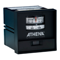
Figure 2b: Typical 120 Vac for -B & -T Output
Typical Wiring Diagrams
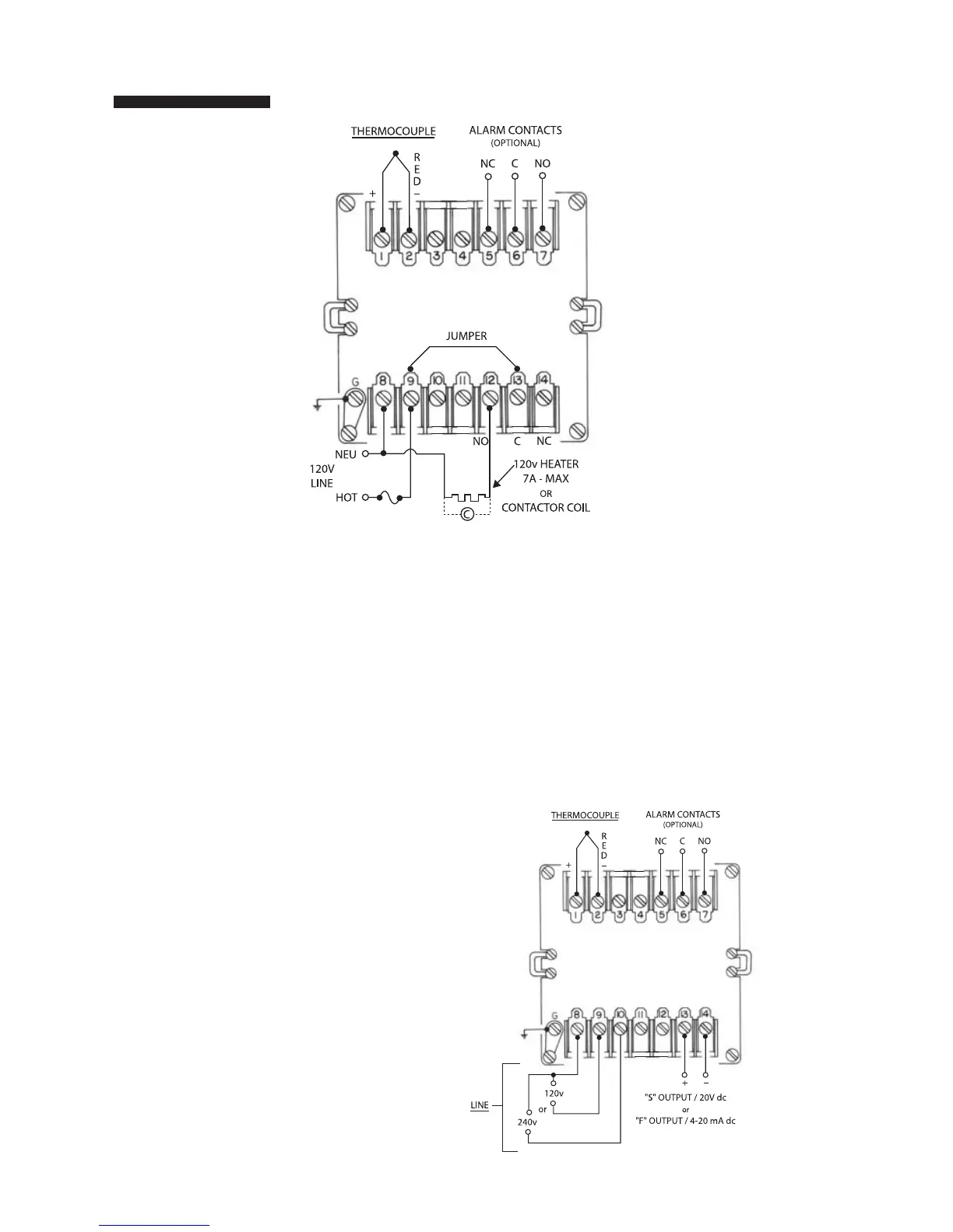
Figure 3: Typical 120/240 Vac
for -F & -S Output
-F, -S Output - 120/240 Vac
The -F output is 20 mA at the low temperature end of the pro-
portional band and 4 mA at the upper end of the proportional
band. Maximum load resistance is 1000 ohms. The -S output
is a time-proportioned 20 Vdc signal. These controllers can-
not be used with a device that does not have an isolated
input. An ungrounded thermocouple must be used if there is
ac leakage or a ground in the input of the device connected
to the controller’s output.
 Loading...