5
Power Wiring
Circuits
Consult serial tag on the unit and select power wiring dia-
gram for the model specified. All wires are connected to the
terminals on the back of the case. Screw terminals are pro-
vided. Make appropriate connections using proper size wire
for rated controller load power circuits. (On -B output model,
use AWG #14 wire; for -F, -S and -T outputs use #14, 16, or
18 wire.) The unit can be supplied with 120 V or 240 Vac,
50/60 Hz. Select proper terminal for the voltage used.
Typical Wiring Diagrams
-T & -B Outputs
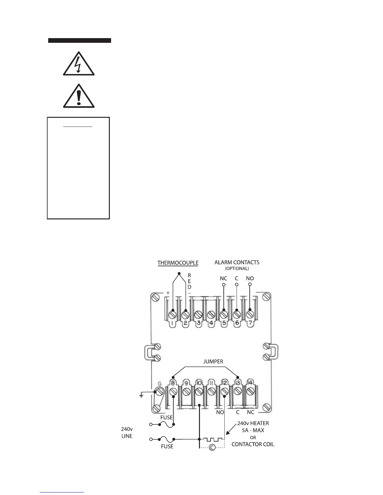
B-Type - 840 W maximum. 120 Vac heater. (Non-inductive
loads only) For larger loads, replace heater connections with
contactor, as required. Maximum inductive load rating is 3 A
at 120 V and 1.5 A at 240 V. The N.C. contacts can be used
for cooling.
T-Type - solid state relay with SPST contacts. The -T units can
handle contactors or resistive loads up to 1 A with 10 A
inrush maximum. For -T units use a 1 A, 250 V fast blow fuse.
-L Output (Limit Controller)
Wiring can be similar to that shown for “B.” The controller’s
relay is de-energized until the reset button on the front panel
is momentarily pressed. The relay will energize if the sensor
temperature is below setpoint. The common and N.C. termi-
nals can be used to indicate alarm condition remotely when
wired to lights, bell, etc.
CAUTION
Possible fire haz-
ard. Because
these controls or
associated equip-
ment may not
always fail safe,
an approved tem-
perature and/or
pressure safety
control should be
used for safe
operation.
Figure 2a: Typical 240 Vac for -B & -T Output
 Loading...