Series S Solid-State Staging Controller Instruction Manual
8
Series S Solid-State Staging Controller Instruction Manual
9
2.2 Module Explanation.
The S Series Staging Controller consists of a main
frame and a large printed circuit board into which are
inserted a variety of input, timing and output stage
boards. For ease of identification and maintenance,
the individual boards are supplied with color coded
handles.
There are labels on each green and yellow handle
describing the exact input and time delay of the
signal conditioner and step delay modules. The label
supplies quick identification of the unit’s operating
modes. On the white, red, and blue stages, a logic
status light (light emitting diode – L.E.D.) can be seen
through the cover in the appropriate box as each
stage is energized.
The status light indicates the operation of the stage,
but is not an indication of the fuse nor the output triac
condition.
Note: Modules should never be placed in the unit
in arbitrary positions or while the controller is
energized.
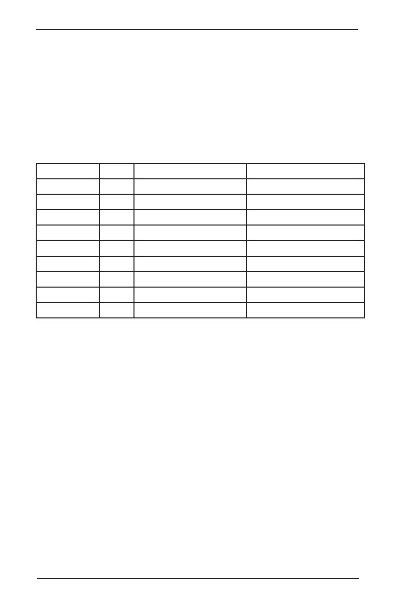
BOARD # CODE DESIGNATION FUNCTION
785A072U01 Green Input Signal Conditioner 4-20 mA; 135 Slidewire (A)
785A073U08 Green Input Signal Conditioner Thermistor Temp. Control (B)
785A074U01 Yellow Step Delay Driver Adj Delay 2-5 to 12 Sec.
785A074U02 Yellow Step Delay Driver Adj Delay 2-7 to 50 Sec.
785A074U03 Yellow Step Delay Driver Adj Delay 2-14 to 100 Sec.
785A078U01 White Circular Mode Output Stge Heating SC Units
785A076U01 Black Circular End Board Completes Circular Loop
785A078U02 Red Up-Down, Heat SU Units
785A078U03 Blue Up-Down, Cool SU Units
 Loading...