♦
Ensure that the hydraulic demolition cutter is
mechanically and hydraulically attached to the
carrier.
♦
Ensure that the cutter jaws are connected by two
half rings on each cutter jaw pair.
♦
Place the assembly rack with the cutter jaw pair
to be fitted within the range of the carrier.
♦
Switch the carrier on.
♦
Lift the hydraulic demolition cutter.
♦
Close the cutter jaw of the hydraulic demolition
cutter.
The hydraulic cylinders extend.
♦
Let the hydraulic demolition cutter hang vertically
on the carrier, do not place it on the ground.
♦
Secure the carrier such that it cannot move
unexpectedly.
♦
Lock the hydraulic cylinders using the two lock
pins (A) delivered with the bolt cage.
♦
Lock the lock pins (A) on both sides with the spring
retaining pins (B) delivered with the bolt cage.
The piston rod sheaths are now prevented from
slipping out.
♦
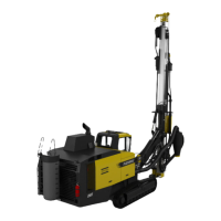
Disassemble the Allen screws (S) and pairs of
lock washers (R).
♦
Remove the covers (C).
♦
Remove the cylinder pins (D).
♦
Remove the spacer rings (E)
♦
Retract the hydraulic cylinder.
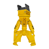
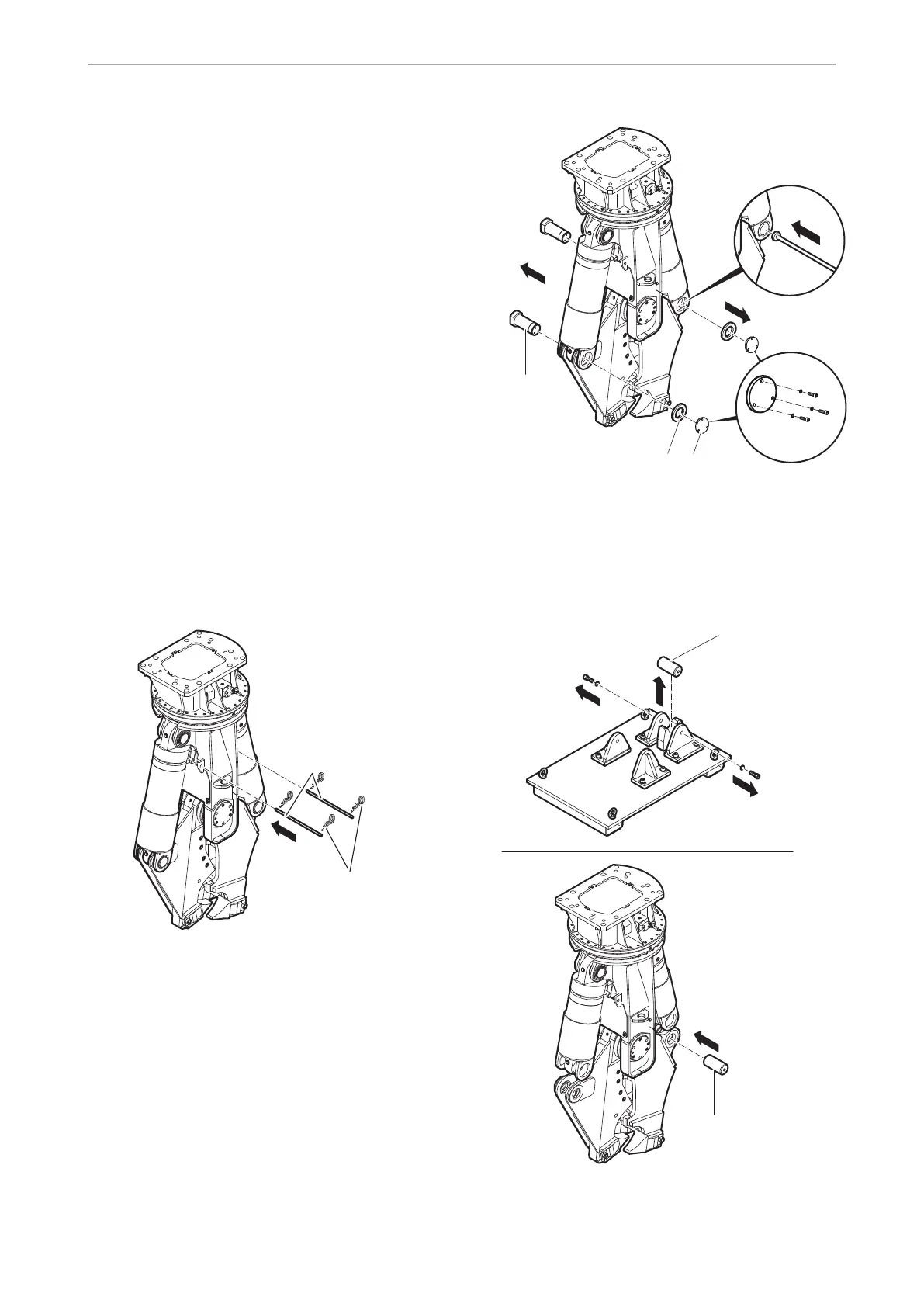
♦
Disassemble the bolts (F) from the empty
assembly rack.
♦
Push the bolts (F) in the cylinder pin bearing of
the cutter jaw (double).
© 2015 Construction Tools GmbH | No. 3390 5141 01 | 2015-11-16
Original instructions
28
CC 1700 U, 1700 SINSTALLATION
 Loading...