If you want to use the feature to “freeze” the regeneration cycle when the compressor runs
unloaded, connect pin 1 and 2 of connector X3 with the potential free contact of the
compressor (contact closed = freeze).
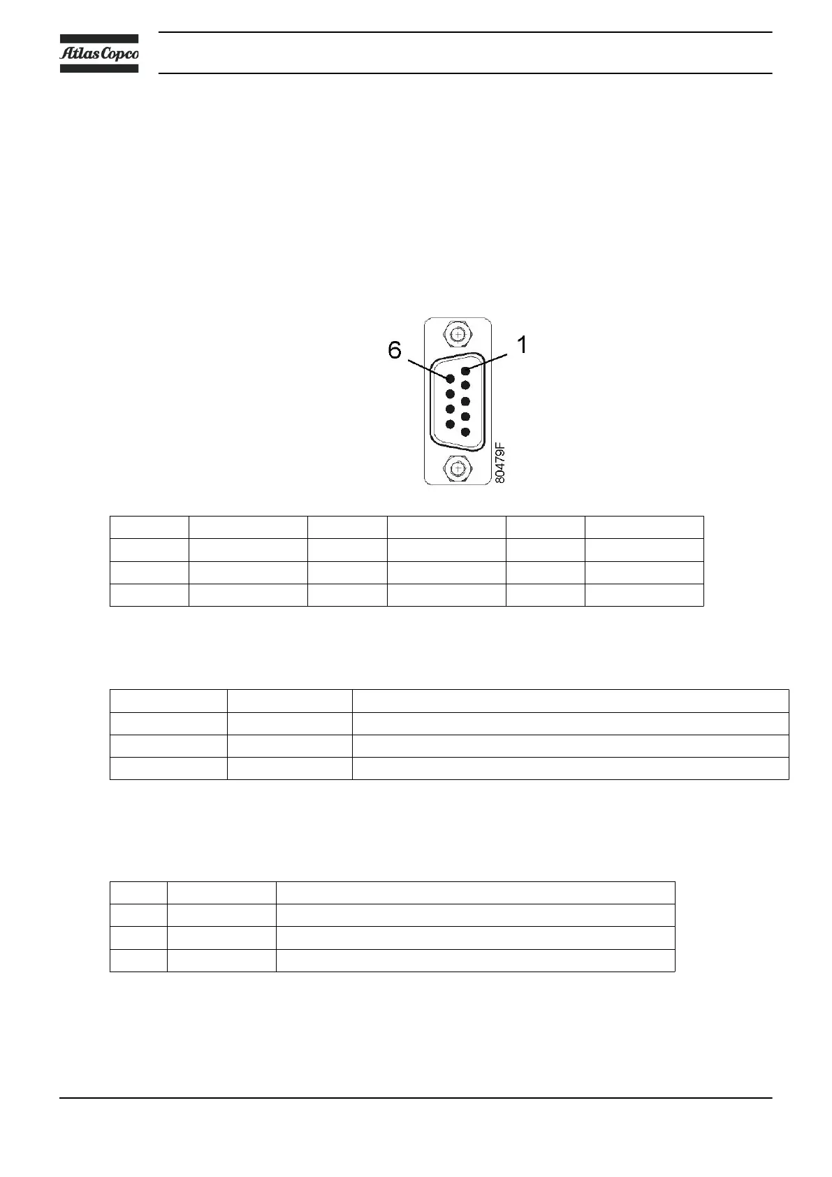
• CAN-Bus connection
The timer card can be interconnected in a LAN with other Elektronikon® controllers.
Addressing and CAN protocol used are the same as for the Elektronikon regulators.
Because the timer card has no programming features however, the exchanged information
is pre-configured and cannot be redefined.
Application: data communication between timer cards, MkIV Elektronikon regulators and
service PC.
Pin Function Pin Function Pin Function
1 reserved 4 reserved 7 CAN_HIGH
2 CAN_LOW 5 reserved 8 reserved
3 CAN_GND 6 CAN_GND 9 reserved
• Output alarm relay X11
These terminals are connected to a relay that switches at the same time as the alarm LED.
Pin designations:
Pin Label Description
1 NO2 Alarm contact - Normally Open
2 COM2 Alarm contact - Common
3 NC2 Alarm contact - Normally Closed
• Output warning relay - X12
These terminals are connected to a relay that switches at the same time as the warning
LED.
Pin designations:
Pin Label Description
1 NO1 Warning contact - Normally Open
2 COM1 Warning contact - Common
3 NC1 Warning contact - Normally Closed
• Configuration dip switch settings
The dip switch settings are factory set and should not be altered unless the timer card is
replaced or an option is fitted.
Instruction book
22 API093050