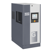
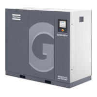
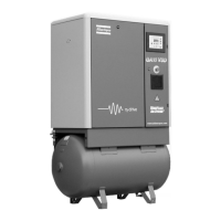
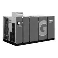
Description
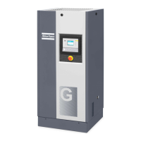
1 Install the compressor unit on a solid, level floor suitable for taking the weight. Recommended
minimum distance between top of the unit and ceiling is 900 mm (35 in). Stated distances
between unit and walls are minimum.
* Recommended distance is 500 mm for easy access.
Air receiver may not be bolted to the ground.
2 Position of the compressed air outlet valve (can be located on both sides of the air receiver).
3 The pressure drop over the air delivery pipe can be calculated as follows:
Δp = (L x 450 x Q
c
1.85
) / (d
5
x P), with
d = Inner diameter of the pipe in mm
Δp = Pressure drop in bar (recommended maximum: 0.1 bar (1.5 psi))
L = Length of the pipe in m
P = Absolute pressure at the compressor outlet in bar
Q
c
= Free air delivery of the compressor in l/s
It is recommended that the connection of the compressor air outlet pipe is made on top of the
main air net pipe in order to minimise carry-over of possible condensate residue.
4 Ventilation: the inlet grids and ventilation fan should be installed in such a way that any
recirculation of cooling air to the compressor is avoided. The maximum air velocity through the
grids is 5 m/s (16.5 ft/s).
Cooling air ducts are not allowed.
The maximum air temperature at the compressor intake is 46 ˚C (115 ˚F) (minimum 0 ˚C / 32
˚F).
The ventilation capacity required to limit the compressor room temperature can be
calculated from:
Q
v
= 0.92 N/ΔT
Q
v
= Required ventilation capacity in m
3
/s
N = Shaft input of compressor in kW
ΔT = Temperature increase in the compressor room in °C
5 Mains cable entry.
To preserve the protection degree of the electric cubicle and to protect its components from dust
from the environment, it is mandatory to use a proper cable gland when connecting the supply
cable to the compressor.
Installation guidelines Medical Air Plant
The installation must be carried out by suitably qualified and competent personnel who fully understand the
standards required when working on a piped Medical Gas Distribution System and are conversant with the
information contained in this manual. Installation of any Medical Air Plant must be carried out strictly in
accordance with the specific General Arrangement Drawing and Wiring Diagram issued herein or with the
Plant.
Medical and Surgical Air Plant must be installed within a Plant Room which provides adequate ventilation
for the cooling of electric motors, bearing in mind that approximately 75% of all energy consumed is dissipated
into the Plant Room as heat energy. At least 500 mm must be allowed between the Plant and any walls or
other obstructions. Specific Plant dimensions must be taken into account especially where access is limited
and additional headroom is required to enable installation. Modular Plant configurations allow for a variety
of installed locations.
An example of a complete Air Plant installation can be found in the Air Plant manual.
Instruction book
2920 7104 10 63

 Loading...
