EasyManua.ls Logo

Atlas Copco GA 160 VSD User Manual

Atlas Copco GA 160 VSD
166 pages
To Next Page IconTo Next Page
Page #1 background imageLoading...
Page #1 background image
GA 110 VSD, GA 132 VSD, GA 160 VSD
Instruction book

Table of Contents

Question and Answer IconNeed help?

Do you have a question about the Atlas Copco GA 160 VSD and is the answer not in the manual?

Atlas Copco GA 160 VSD Specifications

General IconGeneral
ModelGA 160 VSD
CategoryAir Compressor
TypeRotary Screw Compressor
Motor Power160 kW
Working Pressure7.5 - 13 bar
Free Air Delivery at 7.5 bar28.5 m³/min
Drive TypeDirect Drive
Cooling TypeAir Cooled
Voltage400 V

Summary

1 Safety precautions

1.1 Safety icons

Explanation of safety symbols used in the manual.

1.2 Safety precautions, general

General safety guidelines for operating the compressor.

1.3 Safety precautions during installation

Important safety measures to follow during compressor installation.

1.4 Safety precautions during operation

Precautions during operation

Specific safety measures to follow while the compressor is running.

1.5 Safety precautions during maintenance or repair

Precautions during maintenance or repair

Critical safety instructions for performing maintenance and repair tasks.

2 General description

2.1 Introduction

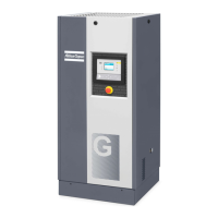
Provides a general view and description of the GA VSD compressors.

DD filter

Describes the integrated DD filter for particle and oil carry-over limitation.

Energy recovery

Explains the system for recovering compression heat as hot water.

2.2 Air and oil system

Position of components

Identifies main components within the compressor unit.

Air flow

Explains the path of air through the compressor system.

Oil system

Describes how oil is circulated and managed within the compressor.

2.3 Cooling and condensate system

Condensate drain system

Details the different types of condensate drains used.

2.4 Energy recovery system

General description

Provides a general overview of the energy recovery system.

Flow diagram

Shows the flow diagram of the energy recovery system.

Installation

Instructions for installing the energy recovery system package.

Calculation examples

Performance curves

Spare parts list

Air-cooled compressors

Lists components and part numbers for air-cooled compressor configurations.

3 Elektronikon regulator

3.1 Elektronikon control system

Details the functions and operation of the Elektronikon control system.

Controlling compressor speed for efficiency

Explains speed control for energy saving and pressure band reduction.

Compressor protection mechanisms

Explains how the system protects the compressor from faults.

Automatic restart function

Explains the automatic restart function after power interruptions.

3.2 Control panel

Parts and functions

Lists and explains the reference numbers for control panel parts.

3.3 Function keys

3.4 Scroll keys

3.5 Emergency stop button

3.6 Control programs

Program Function Overview

3.7 Calling up menus

3.8 Main screen menu

3.9 Status data menu

Shut-down message handling

Explains how shut-down messages are displayed and reset.

Shut-down warning handling

Details shut-down warning messages and their indicators.

Service warning handling

Describes service warnings and required actions.

3.10 Measured data menu

3.11 Counters menu

3.12 Test menu

3.13 Modify parameters

3.14 Modifying compressor/motor settings

Modifying the net pressure setpoints

Instructions for setting desired pressure levels for compressor operation.

3.15 Fan motor settings

3.16 Modifying dryer motor settings

3.17 Modifying parameters

3.18 Modifying protection settings

Compressor element temperature settings

Adjusting temperature settings for compressor element protection.

3.19 Modifying service plans

3.20 Programming clock function

Timer activation and deactivation

How to enable or disable the timer for programmed commands.

Modifying programmed commands

Changing existing programmed commands in the clock function.

3.21 Modifying configuration settings

Compressor control mode programming

Setting compressor control modes: local, remote, or LAN.

3.22 Service menu

Service plan details

3.23 Saved data menu

3.24 Programmable settings

4 Installation

4.1 Dimension drawing

Provides dimensional drawings of the compressor units.

4.2 Installation proposal

4.3 Electric cable size and fuses

4.4 Electric connections

Power distribution system types

Explains electrical connection types based on network system.

4.5 Installation instructions for cubicle fan

4.6 Installation instructions for heavy duty filter for VSD cubicle

4.7 Installation instructions for dryer by-pass

4.8 Installation instructions GSM alarm

4.9 Pictographs

4.10 Cooling water requirements

Ryznar stability index (RSI)

Explains the Ryznar Stability Index for predicting water scaling behavior.

5 Operating instructions

5.1 Initial start-up

Steps for the initial setup and startup procedure.

Protection during transport

Instructions for securing the compressor during transport.

Electric cabinet checks

Checks related to the electric cabinet before operation.

Water circuit pre-operation checks

Checks for the water circuit before starting the compressor.

5.2 Before starting

5.3 Starting

5.4 During operation

5.5 Checking the display

5.6 Stopping

5.7 Taking out of operation

Disconnecting the compressor from service

Steps for disconnecting the compressor at its end of service life.

6 Maintenance

6.1 Preventive maintenance schedule

Detailed schedule for routine preventive maintenance tasks.

Service agreements and plans

6.2 Motors

6.3 Oil specifications

6.4 Oil change

Filling compressor with oil

Procedure for filling oil into the compressor element and air receiver.

6.5 Storage after installation

6.6 Service kits

7 DD filter

7.1 Maintenance

General maintenance guidelines for the DD filter.

7.2 Filter element change

7.3 Service intervals

7.4 Filter disposal

7.5 Reference conditions

7.6 Principal data

8 Integrated dryer

8.1 Condensate drain system

Details the operation of the electronic water drain for condensate removal.

Electronic water drain testing

Procedure for testing the electronic water drain's functionality.

Alarm signal checking

How to check the alarm signal and warnings from the EWD.

8.2 Maintenance instructions

8.3 Problem solving

9 Adjustments and servicing procedures

9.1 Air filters

Procedures for servicing and replacing air filters.

Air filter position and servicing

9.2 Coolers

Cooler cleanliness checking

Method to check cooler cleanliness using pressure drop.

Cooler cleaning procedures

9.3 Safety valve

10 Problem solving

10.1 Problem solving

Troubleshooting guide for common compressor issues.

Service message display troubleshooting

How to handle and reset service messages.

Shut-down warning display troubleshooting

Explains shut-down warnings and their resolution.

Unit shutdown causes and remedies

Reasons for unit shutdown and how to remedy.

Excessive oil consumption troubleshooting

Troubleshooting guide for high oil consumption issues.

11 Technical data

11.1 Readings on display

Lists the data displayed on the regulator's screen.

11.2 Reference conditions

Specifies standard operating conditions for technical data.

11.3 Limits

Lists operational limits for temperature, humidity, and pressure.

11.4 Settings of safety valve

Details the settings for the safety valve based on working pressure.

11.5 Settings of circuit breakers

Recommended settings for circuit breakers based on network system and voltage.

11.6 Compressor data

Provides detailed technical data for various compressor models and configurations.

12 Pressure equipment directives

Category IV classification

Specifies the product's classification under pressure equipment directives.

13 Documentation

Declaration of conformity example

Provides a typical example of a Declaration of Conformity document.

Related product manuals