2920 1381 02
4
Instruction book
1.1.1 Air flow (Fig. 1.6)
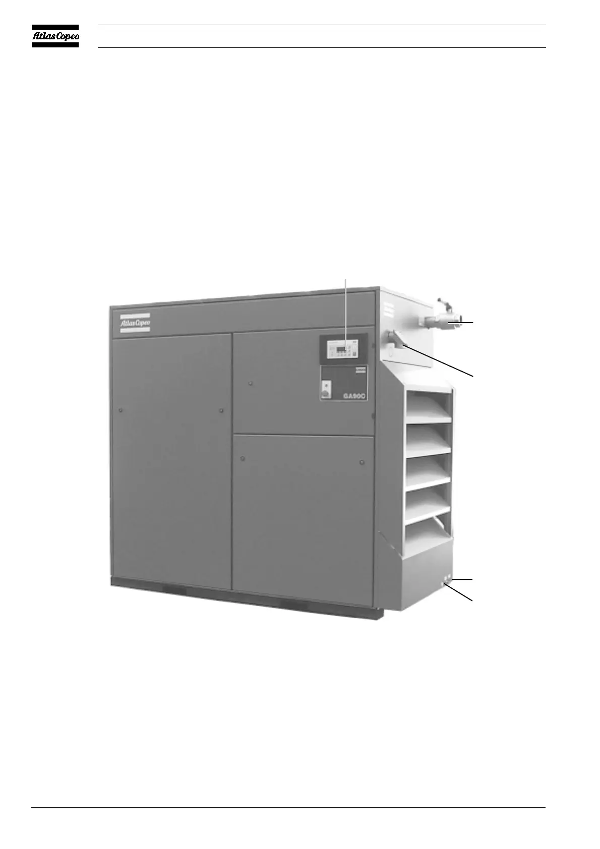
Fig. 1.2 General view of GA90C
AV Air outlet valve
CM Control module
Daa Automatic condensate drain outlet
Dma Manual condensate drain valve
1 Electric cable entry
Figs. 1.1 and 1.2 General views of GA75 and GA90C
Air drawn through filter (AF) and open inlet valve (IV) into
compressor element (E) is compressed. Compressed air and
oil flow into air receiver/oil separator (AR) via check valve
(CV). The air is discharged through outlet valve (AV) via
minimum pressure valve (Vp), air cooler (Ca) and condensate
trap (MTa).
Check valve (CV) prevents blow-back of compressed air when
the compressor is stopped. Minimum pressure valve (Vp)
prevents the receiver pressure from dropping below a minimum
pressure.
CM
Dma
Daa
50507F
1
AV

 Loading...