Instruction book
6996 0227 40 15
Thermostatic bypass valve
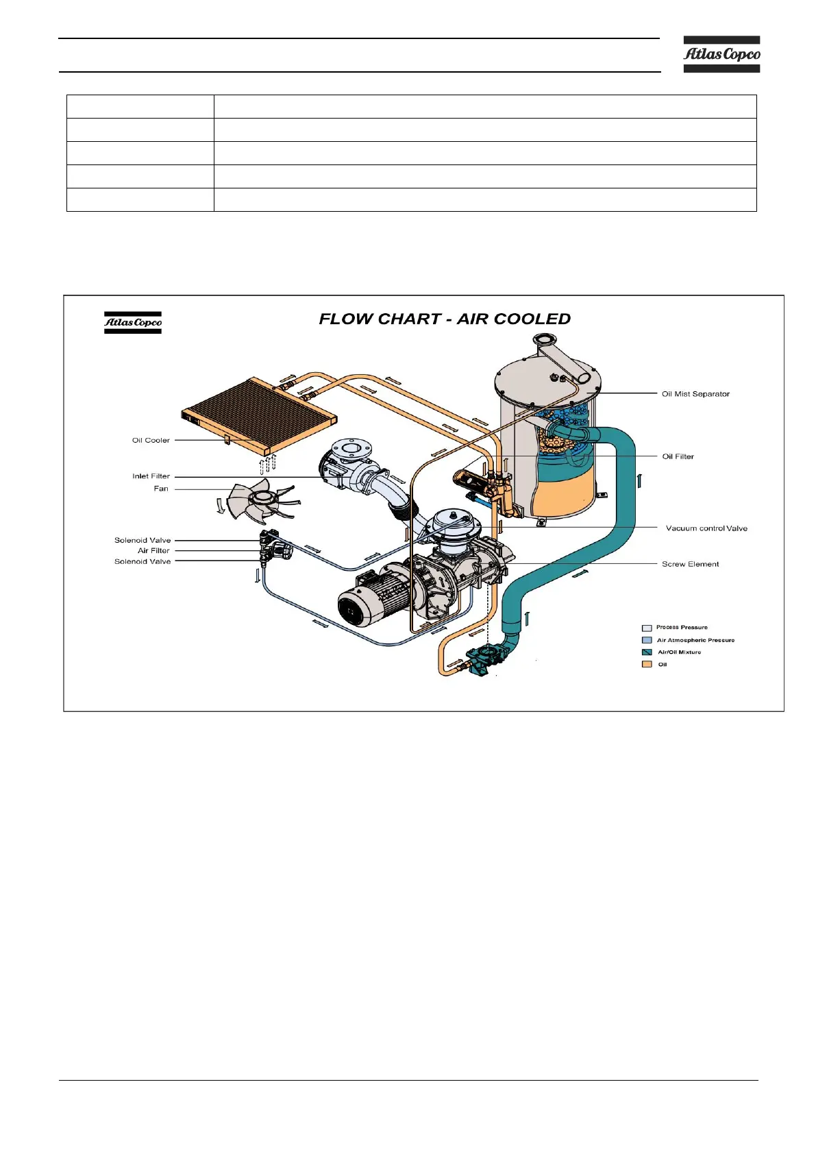
2.3 Flow diagram
Air flow
Air comes in through air intake filter (AF) and Vacuum Control Valve (VC) and is displaced by the
vacuum pump element (E).
A mixture of air and oil flows into the oil separator tank (OT).
After passing the air/oil separator filter, clean air, conditioned to a few parts per million, is discharged
through the outlet.
Oil system
The oil separator tank (OT) removes most of the oil from the air/oil mixture by centrifugal action. The oil
separator (OS) removes the remaining oil. The oil collects in the lower part of the oil separator tank
(OT) which serves as oil tank.
The oil system has a thermostatic bypass valve (BV).When the oil temperature is below 83 °C (181 °F)
(87°C (189°F) for optional high water handling capacity versions), the bypass valve shuts off the oil
supply from the oil cooler (Co).
Air pressure forces the oil from oil separator tank through the oil filter (OF). The oil cooler (Co) is
bypassed. When the oil temperature has increased up to 83 °C (181 °F) (87°C (189° F) for optional
high water handling capacity versions), bypass valve (BV) starts opening the supply from the oil cooler
(Co). At approx. 95°C (203°F) (104°C (219°F) for optional high water handling capacity versions), all
 Loading...