2920 1449 00
25
Instruction book
Important
The regulator will only react to a new control mode if the new
position of the control mode switch is maintained for 3 seconds.
To avoid unauthorized switching over to another control mode,
take out the key after selecting the required mode.
3.1.6 Initial start-up
1. Consult section 2 for the electric cable size, installation
proposal and dimension drawings.
2. Read the "User manual for Elektronikon
®
regulator for GA-
GR-ZE-ZA-ZR-ZT" to familiarize yourself with all
regulator functions.
3. A sticker dealing in short with the operation instructions is
delivered with the literature set. Affix the sticker next to
the control panel.
4. Stick labels near the control panel warning the operator that:
- the compressor may automatically restart after voltage
failure
- the compressor is automatically started and stopped
- the compressor may be remotely controlled.
5. A number of VCI (Volatile Corrosion Inhibitor) plates are
provided inside the bodywork to protect the compressor
against corrosion. Remove the plates.
6. The gear casing supports, motor support and air receiver
supports are secured to the frame, immobilizing the vibration
dampers during transport.
Remove bushes (1-Fig. 3.1) from both gear casing supports
as well as bushes (1-Fig. 3.2) from the motor support. Also
remove the transport bolts fitted next to the air receiver
supports.
7. Check the wires at transformer (T1-Fig. 1.9) for correct
connection, the settings of overload relay (F21) and circuit
breakers (Q25/26) 1), and that overload relay (F21) is set
for automatic resetting. See section 7.4.
8. Remove filler plug (6-Fig. 1.3). Pour approx. 1 l of oil into
the compressor elements. Reinstall the plugs.
9. Close drain valves (1 and 2-Fig. 3.4). 2)
10.For GR W, check that the cooling water drain valves 3) in
the inlet and outlet lines are closed and that the water shut-
off valves 3) are open. Open the water regulating valve (4-
Fig. 3.7) and check for water flow.
11. Check that the compressor is filled with oil: the pointer of
oil level indicator (5-Fig. 3.8) should be in the green range.
12.For GR Full-feature, check that valve (2-Fig. 1.2) is closed
and that valves (1 and 3-Fig. 1.2) are open.
13.For compressors provided with an OSD oil/water separator:
fill the vessel with water to the level of the water outlet and
re-install the cover.
14.Switch on the voltage. Start the compressor and stop it
immediately. Check the rotation direction of the drive motor
(M1-Fig. 1.1) while the motor is coasting to a stop. If the
rotation direction is wrong, switch off the voltage and
reverse two incoming electric lines.
The correct direction of rotation is indicated for the drive
motor by arrow (5-Fig. 1.1) and for the fan motors by arrows
(19-Fig. 1.3) on the motor housings.
3.2 Before starting
Attention
- The operator must apply all relevant safety precautions,
including those mentioned in this instruction book.
- In case the water system was drained (see section 3.7), close
the drain valves.
1. Switch on the voltage. Voltage on LED (2-Fig. 3.5) lights
up.
2. Close condensate drain valves (1 and 2-Fig. 3.4). 2)
3. Open air outlet valve (3-Fig. 3.3).
4. Check oil level indicator (5-Fig. 3.8): the pointer should be
in the green range or orange range 4).
5. For GR Full-feature (provided with an integrated dryer),
check that valve (2-Fig. 1.2) is closed and that valves (1
and 3-Fig. 1.2) are open.
6. On GR W open the water shut-off valves 3) and regulating
valve (4-Fig. 3.7).
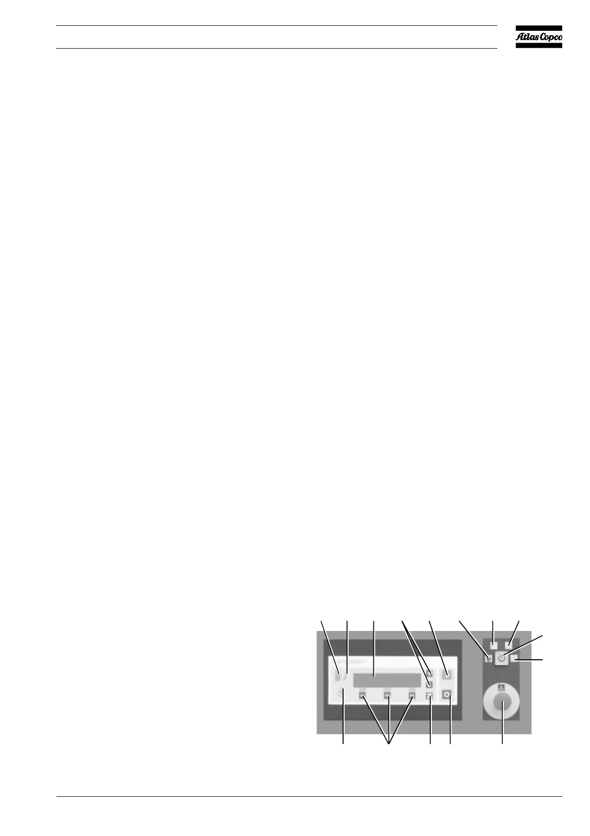
Fig. 3.5 Control panel
124
6
8
S5
S23579
50618F
10
11 12
13
 Loading...