2920 1257 04
40
Instruction book
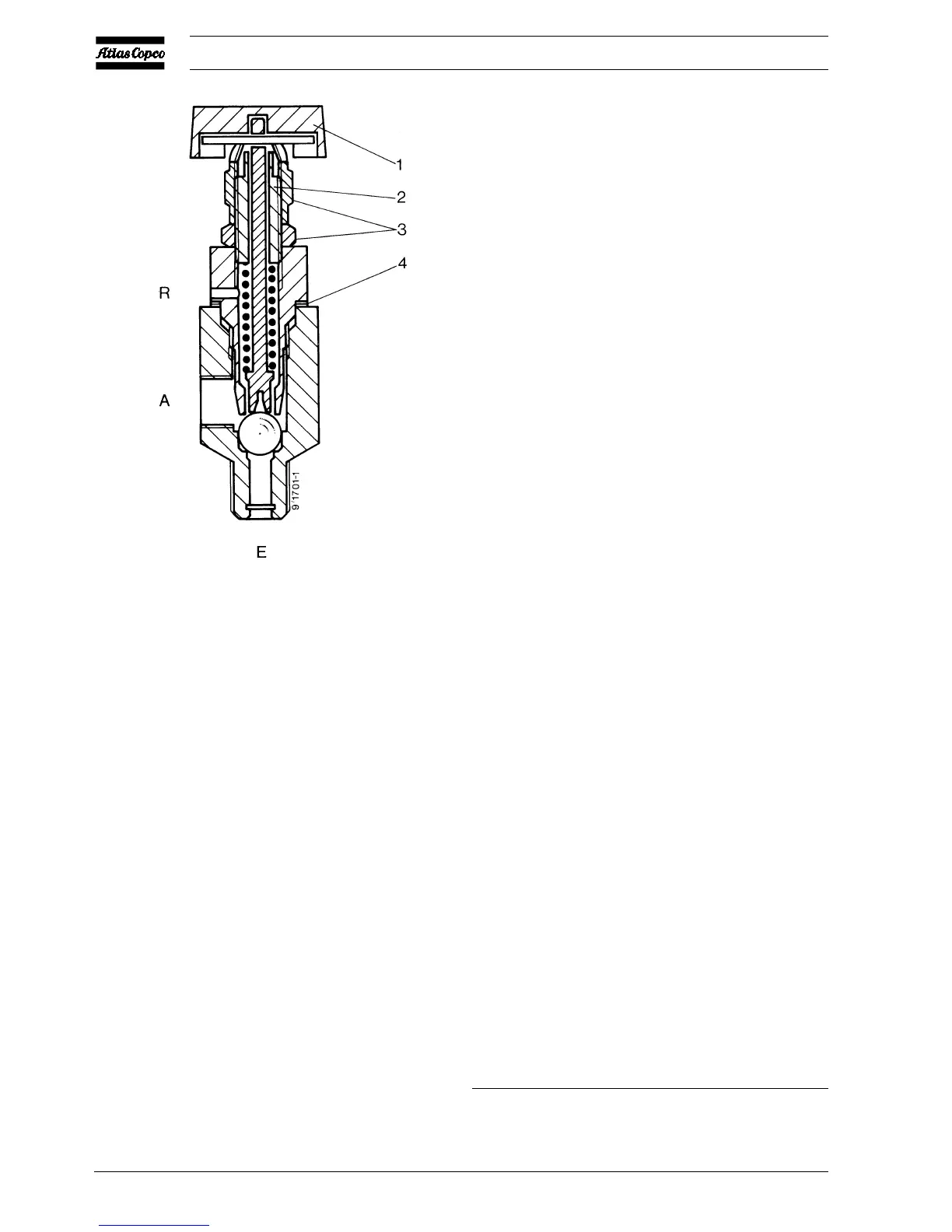
Setting of the pilot valve
The maximum pressure is controlled by adjusting screw (2):
- Loosen handle (1) and the two nuts (3).
- Turn the adjusting screw (2) clockwise to increase the
maximum pressure.
- The pressure difference can be increased by removing one
or more shims (4).
- Fit the two nuts (3) and handle (1) in their original position.
5.7 Safety valve (SV-Figs. 1.4, 1.5 and
1.8) 1)
Replace the valve if it does not open at the correct pressure.
No adjustments are allowed.
A Control air to unloader
E Compressed air from pulsation dampers
R Vent hole
1 Unloading handle
2 Pressure adjusting screw
3 Nuts
4 Shims
Fig. 5.8 Pilot valve on LE/LT Trolley
Testing on LE/LF/LT
1. Close the air outlet valve, depressurize and disconnect the
hose or pipe from the valve.
2. Start the compressor and run it until it stops automatically.
3. Switch off the voltage.
Remove the cover from the air pressure switch and, with
the air receiver now under pressure, turn the adjusting knob
or screw one turn clockwise to increase the stopping
pressure (see also sections 5.4/5.5). Reinstall the cover.
4. Switch on the voltage, slightly open the outlet valve and
start the compressor.
5. Gradually close the outlet valve while checking the air
pressure gauge. If the safety valve has not opened at the
pressure specified in section 7, it must be replaced by a
new one. If the compressor unloads before the specified
opening pressure is reached, repeat the procedure as
mentioned from step 3.
6. Readjust the unloading pressure as described in sections
5.4 and 5.5.
7. Reconnect the hose or pipe to the closed air outlet valve.
Testing on LE/LF/LT Trolley
1. Close the air outlet valves, depressurize and disconnect
the hoses from the valves.
2. Loosen the red handle of the pilot valve (1-Fig. 5.8) and
the two nuts (3).
3. Open outlet valve (AV1-Fig. 1.16) a fraction. Start the
compressor.
4. Gradually turn adjusting screw (2-Fig. 5.8) clockwise while
checking pressure gauge (Gp-Fig. 1.16).
If the safety valve has not opened at the pressure specified
in section 7, it must be replaced by a new one.
5. Readjust the normal working pressure after testing. Consult
section 5.6.
6. Fit nuts (3-Fig. 5.8) and handle (1) in their original
positions.
5.8 Relief valve (8-Fig. 1.1) on LF55/75,
LE75 up to -150 and LT
The relief valve protects the LP side of the compressor. No
adjustments are allowed.
Remove the relief valve and fit a 3/8 inch B.S.P. plug instead.
Remove the safety valve from the air receiver and replace it
by the relief valve. The latter can then be tested at increasing
air receiver pressure after the compressor has been started
with open air outlet valve. If the valve has not opened at the
pressure specified in section 7, it must be replaced by a new
one. Reinstall the valves in their respective places after testing.
Footnote chapter 5
1) Not on Compressor Block/Power Pack
 Loading...