2920 1257 04
8
Instruction book
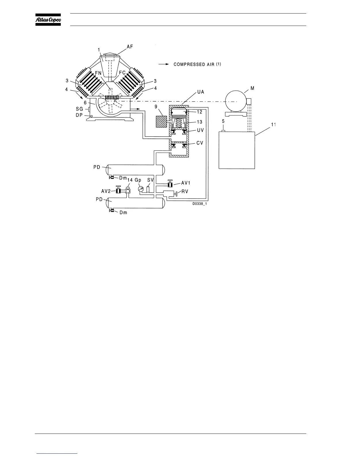
Fig. 1.12 Air flow of LE Trolley and regulating system of LE/LF/LT Trolley
AF Air filter
AR Air receiver
AV Air outlet valve
AV1/2 Air outlet valves
CV Check valve
Dm Condensate drain valve
DP Oil drain plug
FC Oil filler cap
FN Fan
Gp Air pressure gauge
M Motor
MDR Air pressure switch
PD Pulsation damper
RV Pilot valve
SG Oil level sight-glass
SV Safety valve
UA Unloader
UV Unloading valve
Y1 Loading solenoid valve
1 Air inlet silencer
2 Pressure release valve
3 Cylinder
4 Cooler
5 On/off switch
6 Cooling pipe
7 LP cylinder
8 HP cylinder
9 Blow-off silencer
10 Intercooler
11 Electric cabinet
12 Plunger
13 Spring
14 Pressure regulator
Figs. 1.10 up to 1.12 Air flow and regulating systems
1.3.3 LE/LF/LT Trolley (Fig. 1.12)
The regulating system includes:
- Pilot valve (RV)
- Unloader (UA) with integrated check valve (CV)
- Electric cabinet (11) (only on electric motor driven Trolley
compressors)
Operation
Pilot valve (RV) opens and closes at pre-set pressures. During
loaded operation, pilot valve (RV) is closed preventing the
compressed air from flowing to unloader (UA).
When the pressure in the pulsation dampers (PD) reaches the
pre-set maximum pressure, pilot valve (RV) will open.
 Loading...