Industrial Air Division
212920 5997 03
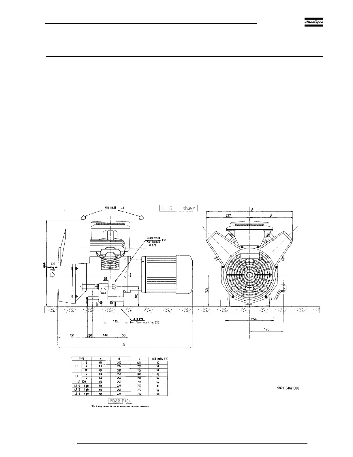
10 Dimension drawings
[1] Air inlet
[2] For floor mounting
[3] Cooling air inlet
[4] Net mass
[5] Compressed air outlet G 1/2
[6] Manual condensate drain
[7] Electric cable entry Pg 16
[8] Electric cable entry Pg 21 (on rear side)
[9] Cooling air outlet
[10] Air receiver must not be bolted on the floor without rubber pads
[11] Shown LE7/8 with 250 l EURO receiver and silencing hood
[12] Female air outlet G 1/2
[13] Compressor cooling air and air inlet
[14] Hole 15 x 24 (4 x), can be used for fixing without rubber pads
Fig. 14. LE5, -6, -6C/LT5, -6, -530 Power Pack
Figs. 14 up to 21. Dimension drawings
 Loading...