Industrial Air Division
2920 5997 03
12
Torque values
M6: 10 Nm
M8: 23 Nm
M10: 45 Nm
5.3 Air filter
Notes
- Never remove the element while the compressor is running.
- Never use damaged elements.
Servicing
1. Unscrew cap (1-Figs. 1). Lift off the cover of the filter element
and the element. Take care that no dirt drops inside the suction
silencer.
2. Using a damp cloth, clean the filter chamber and cover.
3. Install the new element, cover and cap.
5.4 Setting of the air pressure switch
(PSR19-Figs. 1)
The adjustment of the maximum or stopping pressure of the
compressor is effected by means of the air pressure switch. The
switch also controls the pressure drop, i.e. the difference between
the maximum pressure (stopping pressure) and that at which
compression is resumed (starting pressure).
Caution
Adjust the air pressure switch while it is pressurized.
Switch off the voltage before removing the cover of the switch;
reinstall it after an adjustment has been made and before the
voltage is switched on again.
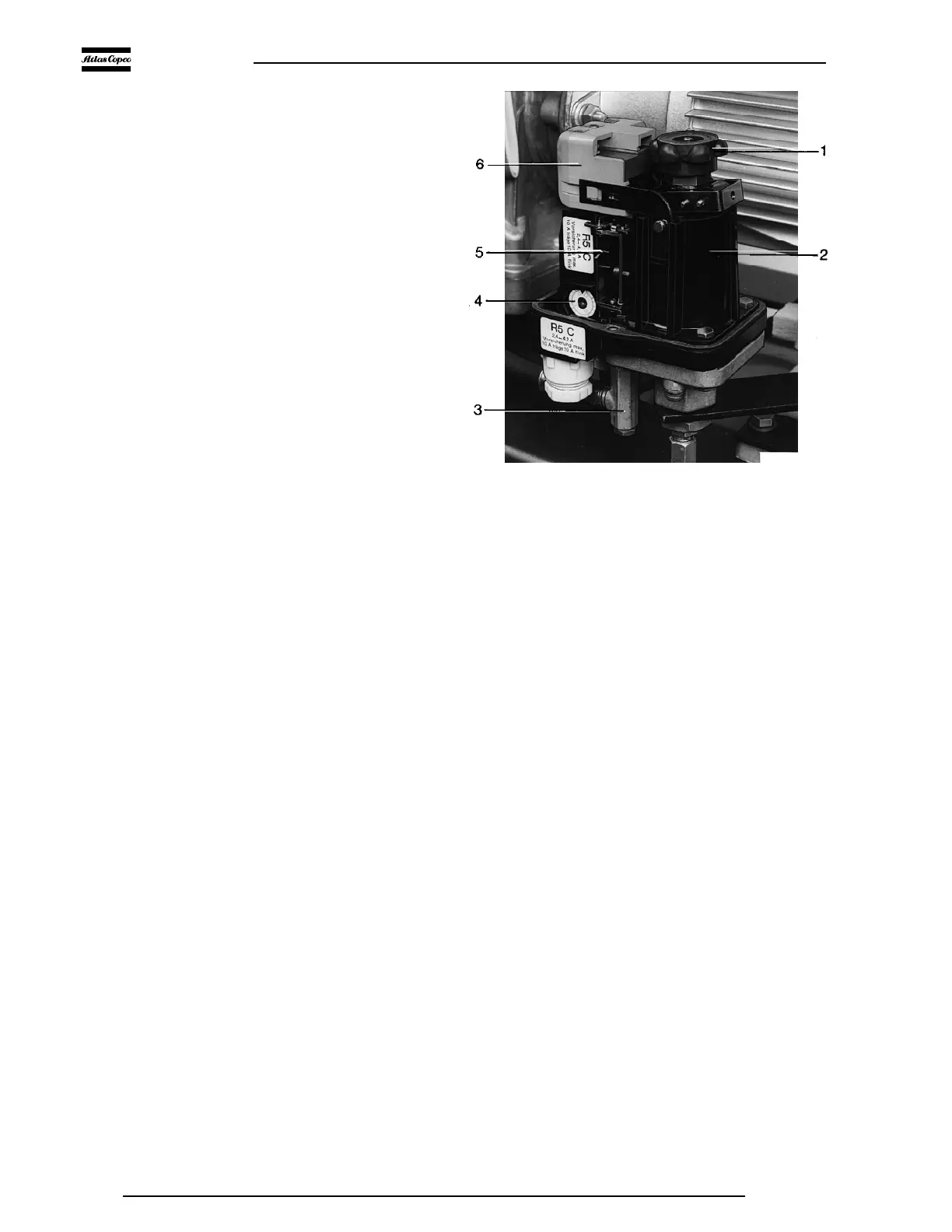
5.4.1 Air pressure switch MDR5 (Fig. 6)
The switch incorporates the motor starter and mostly the overload
protection.
The maximum pressure is controlled by adjusting knob (1).
Turn the knob clockwise to raise the maximum or stopping
pressure, anti-clockwise to lower it.
The pressure difference is adjusted by means of the same knob.
Push down the knob and turn it clockwise to reduce the difference
between the stopping and starting pressures, i.e. to increase the
starting pressure. Turn the knob anti-clockwise to increase the
pressure difference. The adjustment range is shown in the
diagrams (Figs. 7).
5.4.2 Air pressure switch MDR4 (Fig. 8)
The maximum pressure is controlled by adjusting screw (2). Turn
the screw clockwise to raise the maximum or stopping pressure,
anti-clockwise to lower it.
The pressure difference is adjusted by means of screw (3). To
reduce the difference between the stopping and starting pressures,
i.e. increase the starting pressure, turn the screw anti-clockwise.
To increase the pressure difference, turn the screw clockwise. The
adjustment range is shown in the diagrams (Figs. 9).
5.5 Safety valve (12-Figs. 1)
The safety valve must be tested yearly. Replace the valve if it does
not open at the correct pressure. No adjustments are allowed.
Testing
1. Close the air outlet valve, depressurize and disconnect the
hose or pipe from the valve.
2. Start the compressor and run it until it unloads or stops
automatically.
3. Stop the compressor (if necessary) and switch off the voltage.
Remove the cover from the air pressure switch and, with the air
receiver now under pressure, turn the adjusting knob or screw
one turn clockwise to increase the stopping pressure. Reinstall
the cover.
4. Switch on the voltage, slightly open the outlet valve and start
the compressor.
1. Adjusting knob for stopping and starting pressures
2. Spring housing, air pressure switch
3. Pressure release valve
4. Setting dial, overload relay
5. Motor overload relay
6. Three-pole switching mechanism
Fig. 6. Air pressure switch, type MDR5 with ON/OFF switch
F1756
 Loading...