Instruction manual
2954 2100 01 11
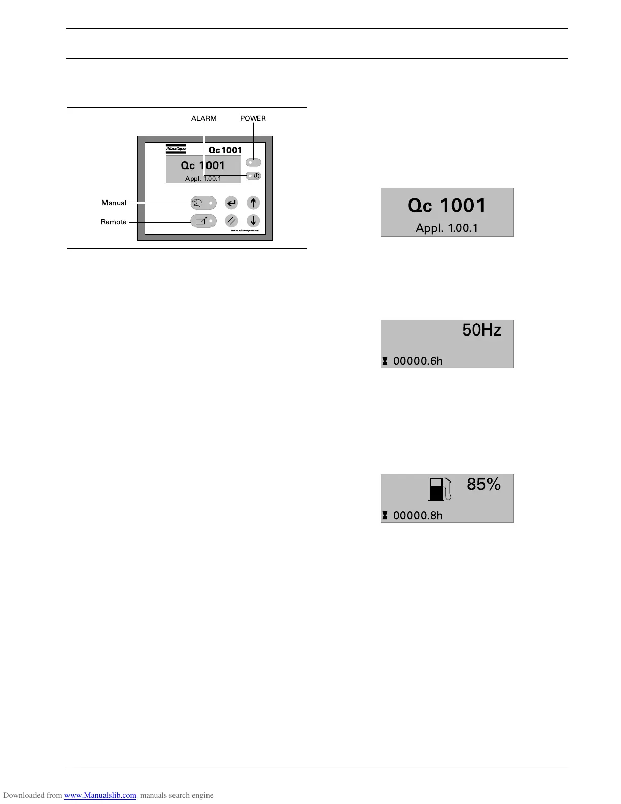
Following LEDs are used on the Qc1001™:
2.5.4 Qc1001™ Menu Overview
At Qc1001™, the LCD will show following information:
–in Normal condition (scroll through the information using UP and
DOWN):
- Status (eg: preheat, crank, run, cooldown, ext. stop, …)
- Running hours
- Battery Voltage
- Service Timer 1
- Service Timer 2
- Generator Frequency
–in Warning condition (scroll through the information using
UP and
DOWN):
- a list of all active Warnings
–in Shutdown condition:
- the cause of shutdown
It's possible to scroll through the views, using the UP and DOWN
buttons. The scrolling is continuous.
If a Special status comes up, the Status Display is shown.
If a Warning comes up, the Warning Display is shown.
If a Shutdown comes up, the Shutdown Display is shown.
View 0
This view will show the ASW version number.
When there has been no button activity for three minutes, the
display will return to the Default View.
View 1 (Qc1001™-Default Display)
The frequency value is centered in the top-right corner area.
The running hours value is at the bottom-left corner. The service
timer indication(s) are shown in the bottom-right corner when the
service timer(s) have run out. They will disappear when the service
timer(s) have been resetted.
View 2 (Fuel Level Display)
This view shows the fuel level icon.
When the English text view is selected, this view will mention:
"FUEL LEVEL ***%".
When there has been no button activity for three minutes, the
display will return to the Default View.
Power: Green LED indicates that the unit is powered up.
Manual: Green LED indicates that the Manual Mode is
selected.
Remote: Green LED indicates that the Remote Mode is
selected.
Alarm: Flashing red LED indicates that a shutdown is
present. Continuous red LED indicates a warn-
ing. The exact warning/shutdown is shown at the
display.
www.atlascopco.com
!
3?
3?
50Hz
00000.6h
85%
00000.8h
 Loading...


