A series of jumpers control how the relays function. There is one
jumper for each relay (JP8-JP10). These jumpers will allow each
relay to either be normally open or normally closed. Relays may
be wetted with +24VDC or be dry contacts depending upon the
setting of jumper JP5.
There is a software setting that controls whether the relays come
on momentarily or remain latched at the end of a cycle.
The inputs are all optically isolated. Each opto-isolator has a
1.5K input impedance, which will work well if +24VDC signals
are used to assert the inputs. When connected, jumper JP3 makes
the opto-inputs common with the system ground. When removed,
the opto-isolators are completely isolated and inputs need to be
referenced to PIN 7, OPTO COM.
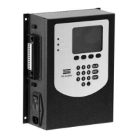
Remote Transducer Connector
The remote pressure transducer plugs into the bottom most RJ11
connector as seen in the picture above. The pin-out for that con-
nector is as follows:
1 +5VDC
2 ANALOG SIGNAL IN
3 RS-485+
4 RS-485-
5 GND
6 N/C
25 RE Qualifier System Manual
 Loading...