Step Action
1 Fit the water drain plugs (DP2 up to DP6) that are attached to the water pipe of one of
the compressor elements (El and Eh) in a plastic bag. The plugs are painted green and
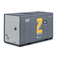
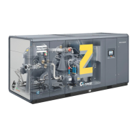
their positions are shown on the illustrations above.
2 Check that the cooling water drain valves (customer's installation) in the inlet and outlet
lines are closed.
3 Open the water inlet valve and outlet valve (customer's installation) and check for water
flow.
4 Check the water flow.
Oil circuit
Position of oil level sight-glass on ZR 110 up to ZR 275
Instruction book
244 2920 1815 04

 Loading...
