Instruction book
2920 1472 03 45
6. The compressor and motor are secured to the frame, immobilizing the vibration dampers
during transport (Figs. 3.1). After installing the compressor:
a On earlier production units (Fig. 3.1a) loosen the nuts (2 and 4) of the long central
bolt of each damper, screw the bolts (1 and 3) as far out as indicated and tighten the
nuts again.
b On recent production units, remove the transport fixations (Fig. 3.1b), which are
painted red. Unscrew bolt (1) and remove transport bush (5). Four transport fixations
are provided: two at the gear casing side and two at the motor side.
7. Check that the gear casing is filled with oil: the level should be in the middle of sight-glass
(SG-Fig. 3.3).
8. Check that the electrical connections correspond to the local codes. The installation must be
earthed and protected by fuses in all phases. An isolating switch must be provided.
9. Check the connections at the primary sides of transformers (T1 and T2-Fig. 1.9). Check the
settings of circuit breaker (Q15) and overload relay (F21).
10. Close the manual drain valve of the condensate trap (1-Fig. 3.5).
On ZR only:
11. Check that the cooling water drain valves (customer’s installation) in the inlet and outlet lines
are closed. Open the water inlet and outlet valves (customer’s installation) and check for water
flow. Open the water flow regulating valves (1 and 4-Fig. 3.6 and 7-Fig. 3.7 in case of IMD).
On compressors with an IMD dryer only:
12. Close the regeneration air inlet valve (2-Fig. 1.5), as well as the air inlet and outlet valves (7
and 10-Fig. 1.5). Open the by-pass valve (9-Fig. 1.5).
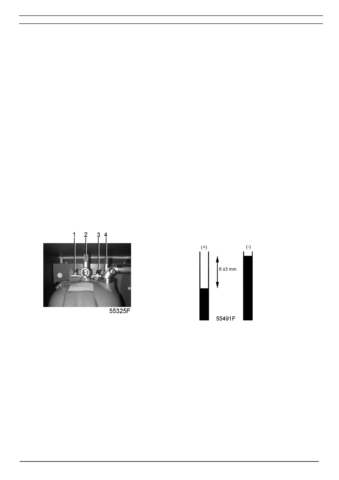
13. Close the valves (1 and 3-Fig. 3.2a). Fill a transparent tube halfway with water. Install the
tube to these valves.
14. Close the manual drain valve (8-Fig. 1.5).
1 Valve for + connection, pressure differential gauge
2 Safety valve
3 Valve for - connection, pressure differential gauge
4 Adjusting screw
Fig. 3.2a Components of IMD dryer, new version
Fig. 3.2b U-Tube
On all compressors:
15. Switch on the voltage. Start the compressor and stop it immediately. Check for correct
direction of rotation while the motor is coasting to a stop. Arrow (1-Fig. 3.3) on the gear
casing indicates the correct rotation direction. If the rotation direction is wrong, switch off the
voltage and reverse two incoming electric lines. On ZT, check the rotation direction of the fan
motor. Cooling air must be blown through the outlet grating on the roof. If the rotation
direction is wrong, switch off the voltage and reverse two connections at the terminals of
circuit breaker (Q15-Fig. 1.9).
 Loading...