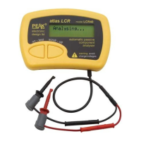
The Peak Atlas LCR40 is an advanced automatic LCR meter designed to simplify the testing of passive components. Unlike traditional LCR bridges, which can be complex and time-consuming, the LCR40 automates component identification, value measurement, and optimal test parameter selection.
Function Description:
The LCR40 automatically identifies the type of component under test (inductor, capacitor, or resistor) and then measures its value. It selects the best signal level and frequency for the specific component, ensuring accurate results. All internal calculations are performed using floating-point mathematics, and results are displayed in properly formatted engineering units (e.g., 23.6pF). The device is designed for analyzing discrete, unconnected components.
Important Technical Specifications:
All values are at 20°C unless otherwise specified.
-
Resistance:
- Range: 1Ω to 2MΩ
- Resolution: 0.3Ω (typical 0.6Ω)
- Accuracy: Typically ±1.0% ±1.2Ω (for resistances between 10Ω and 1MΩ, within 12 months of factory calibration, at temperatures between 15°C and 30°C).
- Measurement Method: DC signal with a peak voltage of 1V (across an open circuit) and a peak current of about 3mA (through a short circuit).
-
Capacitance:
- Range: 0.5pF to 10,000μF
- Resolution: 0.2pF (typical 0.5pF)
- Accuracy: Typically ±1.5% ±1.0pF (for capacitances between 200pF and 500nF, within 12 months of factory calibration, at temperatures between 15°C and 30°C).
- Measurement Methods: AC impedance analysis for low value capacitors (<1μF) using 1kHz, 15kHz, or 200kHz sine wave signals; DC charge analysis for larger capacitors (1μF to 10,000μF).
- Minimum capacitance resolution: About 0.2pF.
-
Inductance:
- Range: 1μH to 2H
- Resolution: 0.4μH (typical 0.8μH)
- Accuracy: Typically ±1.5% ±1.6μH (for inductances between 100μH and 100mH, within 12 months of factory calibration, at temperatures between 15°C and 30°C).
- Measurement Method: Automatic test frequency selection from 1kHz, 15kHz, or 200kHz.
- Minimum inductance resolution: 0.4μH.
- DC Resistance of Inductor: Measured from 0.5Ω to 1kΩ with a minimum resolution of 0.3Ω.
-
Test Frequencies:
- Automatic selection from DC, 1kHz, 15kHz, and 200kHz.
- Test frequency accuracy: -1.5% to +1.5% for 1kHz, 14.925kHz, and 200kHz.
- Sine purity: Typically -60dB 3rd harmonic.
-
Test Signals:
- Peak test voltage (across O/C): -1.05V to +1.05V.
- Peak test current (thru S/C): -5.0mA to +5.0mA.
-
Environmental & Power:
- Operating temperature range: 15°C to 35°C (subject to acceptable LCD visibility).
- Battery operating voltage: 8.5V to 13V.
- Battery life: Typically ~1600 operations (based on <1 minute duration per operation).
Usage Features:
The LCR40 is designed for ease of use with automatic operation and clear result display.
- Automatic Component Identification: The device automatically determines if the component is an inductor, capacitor, or resistor based on its electrical characteristics.
- Automatic Test Frequency Selection: The LCR40 intelligently selects the most appropriate test frequency (DC, 1kHz, 15kHz, or 200kHz) for the component under test to achieve the best measurement resolution.
- Delayed or Instant Analysis:
- Delayed Analysis: Pressing the "on-test" button powers up the unit and initiates a 5-second delay before analysis begins. This allows users to position probes hands-free.
- Instant Analysis: Pressing the "on-test" button again during the 5-second delay will start the analysis immediately.
- Auto Power-Off: The unit automatically switches off after approximately 60 seconds of inactivity (following the last keypress) to conserve battery life.
- Manual Power-Off: Users can manually switch off the device by holding down the "scroll-off" button for about 1 second.
- Scrolling Through Results: Results are displayed one screen at a time. Pressing the "scroll-off" button advances to the next screen. The component does not need to remain connected after analysis is complete.
- Probe and Test Lead Compensation: This crucial feature accounts for the inductance, capacitance, and resistance of the test probes themselves. It involves a short procedure:
- Short the probes together with a tinned copper wire.
- Press and hold "on-test" until "Probe Compensation" is displayed.
- Follow prompts to short and then open the probes.
- Successful compensation displays "OK" and switches off. This ensures subsequent measurements reflect only the component's characteristics. This is particularly important for low-value components.
- Interchangeable Probe Sets: The LCR40 uses 2mm connectors, allowing for various probe sets, including SMD tweezers (SMD03) for surface mount devices.
- Automatic Ranging and Scaling: Results are automatically scaled and displayed in appropriate engineering units (e.g., pF, nF, μF for capacitance; μH, mH, H for inductance; Ω, kΩ, MΩ for resistance).
Maintenance Features:
The LCR40 is designed for minimal maintenance, primarily focusing on battery care.
- Battery Replacement:
- The LCR40 uses a 12V alkaline battery (e.g., 23A, V23A, GP23A, MN21, L1028).
- The battery should be replaced at least every 12 months to prevent leak damage.
- A "Low Battery" message indicates the need for replacement, as measurements may be adversely affected.
- To replace, unscrew the three screws on the rear panel, remove the old battery, insert a new one with correct polarity, and carefully replace the panel.
- A GP23A battery typically provides about 27 hours of operation, or 1600 one-minute operations.
- Self-Tests: The unit performs internal self-tests upon power-up. If performance limits are not met, an error message (e.g., "Error 02") will be displayed, and the unit will switch off. Restarting may clear temporary issues; persistent errors require contacting support. Note that low battery conditions can prevent some internal tests from being performed accurately.
- Calibration: The device is factory calibrated. Full re-calibration and/or certification of traceable calibration can be requested within 12 months of purchase. A "Calibration Due Date" is a recommendation, and the LCR40 will continue to function after this date.
Important Warnings:
- NEVER connect the LCR40 to powered equipment/components or components with any stored energy (e.g., charged capacitors). Failure to comply can result in personal injury, damage to the equipment under test, damage to the LCR40, and invalidation of the manufacturer's warranty. "Analysis of discrete, unconnected components is recommended."
- Capacitors, especially electrolytics, can store significant charge. It is vitally important to fully discharge capacitors (ideally for several seconds) before testing to prevent damage to the LCR40. If unsure, measure the voltage across the capacitor with a voltmeter first.
- The LCR40 is designed for specific component types (inductors, capacitors, resistors). Testing other component types or networks may yield erroneous results.
- Peak Satisfaction Warranty: Within 14 days of purchase, if not completely satisfied, the unit can be returned to the distributor for a full refund, provided it is in perfect condition.
- Statutory Warranty: A 24-month warranty from the date of purchase covers repair or replacement due to defects in materials and/or manufacturing faults. This warranty does not cover: operation outside the user guide's scope, unauthorized access/modification (except battery replacement), accidental physical damage/abuse, or normal wear and tear. Proof of purchase is required for claims.
- WEEE Compliance: The LCR40 complies with Waste of Electrical and Electronic Equipment (WEEE) regulations. It must not be disposed of with general waste but should enter a proper recycling process according to national laws.