8
atlona.com
Toll free: 1-877-536-3976
Local: 1-408-962-0515
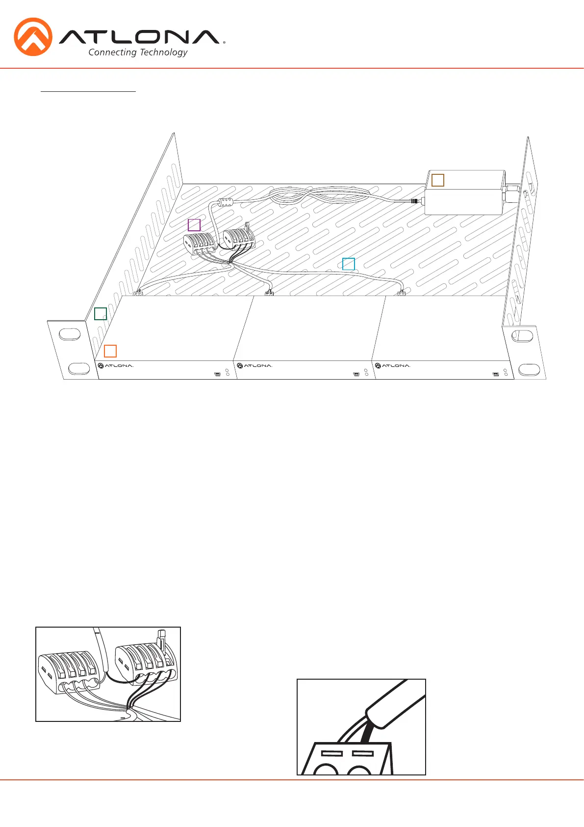
Power Chaining
Multiple kits can be powered by one power supply. The included power supply can support up to 3 kits.
To chain one power supply to three transmitters (four when using AT-PSU-48V1.25A), use two Wago
splicing connectors, 18/2 AWG stranded wire, a ventilated 1 RU rack shelf, zip ties, and high temperature
hook and loop (velcro) strips will be needed.
1. 1 RU rack shelf - Should be at least 10in / 254mm deep, fit in a standard 19” rack, and must be well
ventilated. Use the rack screws (included with 19” racks) to secure the rack shelf to the
back/front of the rack after power chaining set up is completed.
2. Transmitters - Place 3 units on the rack shelf. Use high temperature (up to 185°F / 85°C) hook and loop
(velcro) to secure the transmitters to the rack.
3. Power supply - Place the included power supply on the rack with enough room to connect the included
IEC power cable. Use twist ties to secure the power supply and cable to the rack.
4. Wago splicing connectors - Connect the wires from the power supply cable to the Wago splicers. Connect
(model #: 222-415) the white wire (power/+) to one splicer and the black wire (ground/-) to the
second splicer.
Note: Only one wire per port.
5. 18/2 AWG stranded wire - Connect the individual wires to the Wago splicers and the transmitter captive
screw connectors. There will be two colors of wires (black/red) which will need
to be designated - and +. Each color will need to be the same across all
connections to ensure no signals are crossed. Strip the ends of each wire and
place one end in the appropriate Wago connector and the other to the
corresponding captive screw connector. Use the zip ties to keep all wires
in place and organized.
FW
LINK
POWER
AT-UHD-EX-100CEA-TX
FW
LINK
POWER
AT-UHD-EX-100CEA-TX
FW
LINK
POWER
AT-UHD-EX-100CEA-TX
5
4
3
2
1
Power cable
-
-
-
-
+
+
+
+
18/2 AWG stranded wire
 Loading...