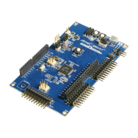
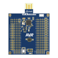
3. Xplained Pro
Xplained Pro is an evaluation platform that provides the full Atmel microcontroller experience. The
platform consists of a series of Microcontroller (MCU) boards and extension boards which are integrated
with Atmel Studio, have Atmel Software Framework (ASF) drivers and demo code, support data
streaming, and more. Xplained Pro MCU boards support a wide range of Xplained Pro extension boards
which are connected through a set of standardized headers and connectors. Each extension board has
an identification (ID) chip to uniquely identify which boards are connected to an Xplained Pro MCU board.
This information is used to present relevant user guides, application notes, datasheets, and example
code through Atmel Studio.
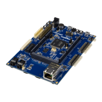
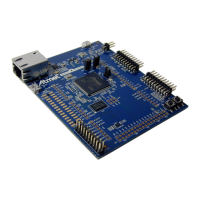
3.1. Embedded Debugger
The SAM C21 Xplained Pro contains the Atmel Embedded Debugger (EDBG) for on-board debugging.
The EDBG is a composite USB device of three interfaces; a debugger, Virtual COM Port, and a Data
Gateway Interface (DGI).
Together with Atmel Studio, the EDBG debugger interface can program and debug the ATSAMC21J18A.
On SAM C21 Xplained Pro, the SWD interface is connected between the EDBG and the
ATSAMC21J18A.
The Virtual COM Port is connected to a UART on the ATSAMC21J18A and provides an easy way to
communicate with the target application through terminal software. It offers variable baud rate, parity, and
stop bit settings. Note that the settings on the ATSAMC21J18A must match the settings given in the
terminal software.
Info: If not set automatically, data terminal ready (DTR) must be set in the terminal software.
The DGI consists of several physical interfaces for communication with the host computer.
Communication over the interfaces is bidirectional. It can be used to send events and values from the
ATSAMC21J18A or as a generic printf-style data channel. Traffic over the interfaces can be timestamped
on the EDBG for more accurate tracing of events. Note that timestamping imposes an overhead that
reduces maximal throughput. Atmel Data Visualizer is used to send and receive data through DGI.
The EDBG controls two LEDs on SAM C21 Xplained Pro; a power LED and a status LED. Table 3-1
EDBG LED Control on page 7 shows how the LEDs are controlled in different operation modes.
Table 3-1 EDBG LED Control
Operation mode Power LED Status LED
Normal operation Power LED is lit when power is
applied to the board.
Activity indicator, LED flashes
when any communication
happens to the EDBG.
Bootloader mode (idle) The power LED and the status LED blinks simultaneously.
Bootloader mode (firmware
upgrade)
The power LED and the status LED blinks in an alternating pattern.
For further documentation on the EDBG, see the EDBG User Guide.
Atmel SAM C21 Xplained Pro [USER GUIDE]
Atmel-42460C-SAM C21 Xplained Pro_User Guide-10/2015
7
Downloaded from Arrow.com.Downloaded from Arrow.com.Downloaded from Arrow.com.Downloaded from Arrow.com.Downloaded from Arrow.com.Downloaded from Arrow.com.Downloaded from Arrow.com.