Operation Instructions
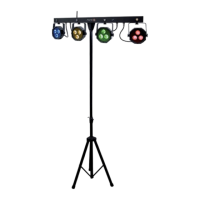
Product operation diagram
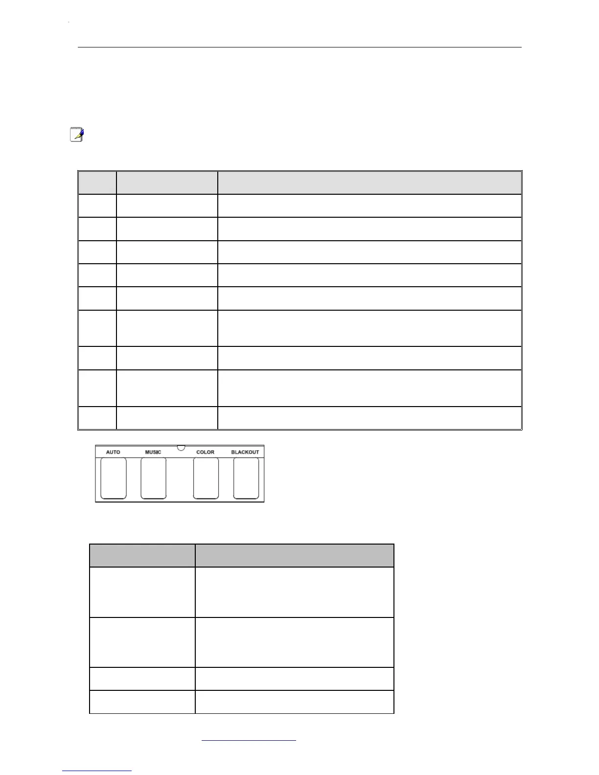
Footswitch Operation Instruction
NOTE:All the operations from the footswitch is invalid to the DMX mode and the SLAVE mode.
NO FUNCTION DESCRIPTION
1 LED PAR lights 12*Tri-9W
2 LED strobe lights 4*1W white LED strobe lights
3 DMX input/output 3PIN male/female XLR interface,for DMX communication
4 Power connection Power output connect with next light
5 Power input Power input socket, built-in protective tube and spare tube
6 Microphones
Receiving the audio signal through a microphone, and positive re-
sponse to the intensity by the potentiometer
7 Potentiometer To adjust the sound activated sensitivity
8
LCD control interfa-
ce Various mode setting operations of the machine
9 Wireless antenna Receiving wireless footswitch signal
NAME FUNCTION
AUTO Press AUTO to activate the auto program
controls. When working, all the lights will
begin in auto mode.
SOUD Press SOUND to activate the sound pro-
gram controls. When working, all the
lights will begin in sound mode.
COLO Color setting: R-G-RG-B-RB-GB-RGB
BLACKOUT Light off.
Atomic4Dj PLS4 Wireless – www.Atomic4Dj.com 7