TH146-N-2H1C 2/8
1) Choose a location about 1.5 m (5 ft) above the floor on an
inside wall.
2) Loosen the captive screw under the console.
3) Detach the console from its base by pulling the bottom section.
4) Secure the base using the wall anchors and screws.
5) Connect the console to controller terminals TH and TH (no
polarity).
The terminals used to connect the heating/cooling system depend
on the type of system. See the appropriate wiring table on page 4.
If you have an add-on installation, you may need an RC845 relay to
connect the furnace (auxiliary heat) and its fan to the controller.
Install the relay near the control module and connect the wires as
follows:
• relay terminals W, G and C to controller terminals W, G and
C.
• relay terminals T and T to the appropriate furnace terminals:
T and T (oil); TH and TH (gas); R and W (electric).
NOTE: Refer to the relay’s installation instructions for more details.
Connect the humidifier in series with the power supply between
controller terminals H and H (dry contact).
The outdoor sensor is required for the following:
• outdoor temperature display
• balance points (heat pumps only, see section 4.2)
• defrost point (heat pumps only, see section 4.3)
• automatic humidity control (see user guide)
When installing the sensor, observe the following guidelines:
• Avoid locations where the sensor can be covered with snow
or exposed to direct sunlight.
• Avoid air outlets and concealed chimneys or stove pipes.
Install the sensor using its mounting clip and connect it to controller
terminals OS and CS (no polarity).
NOTE: The maximum wiring length is 30 m (100 ft).
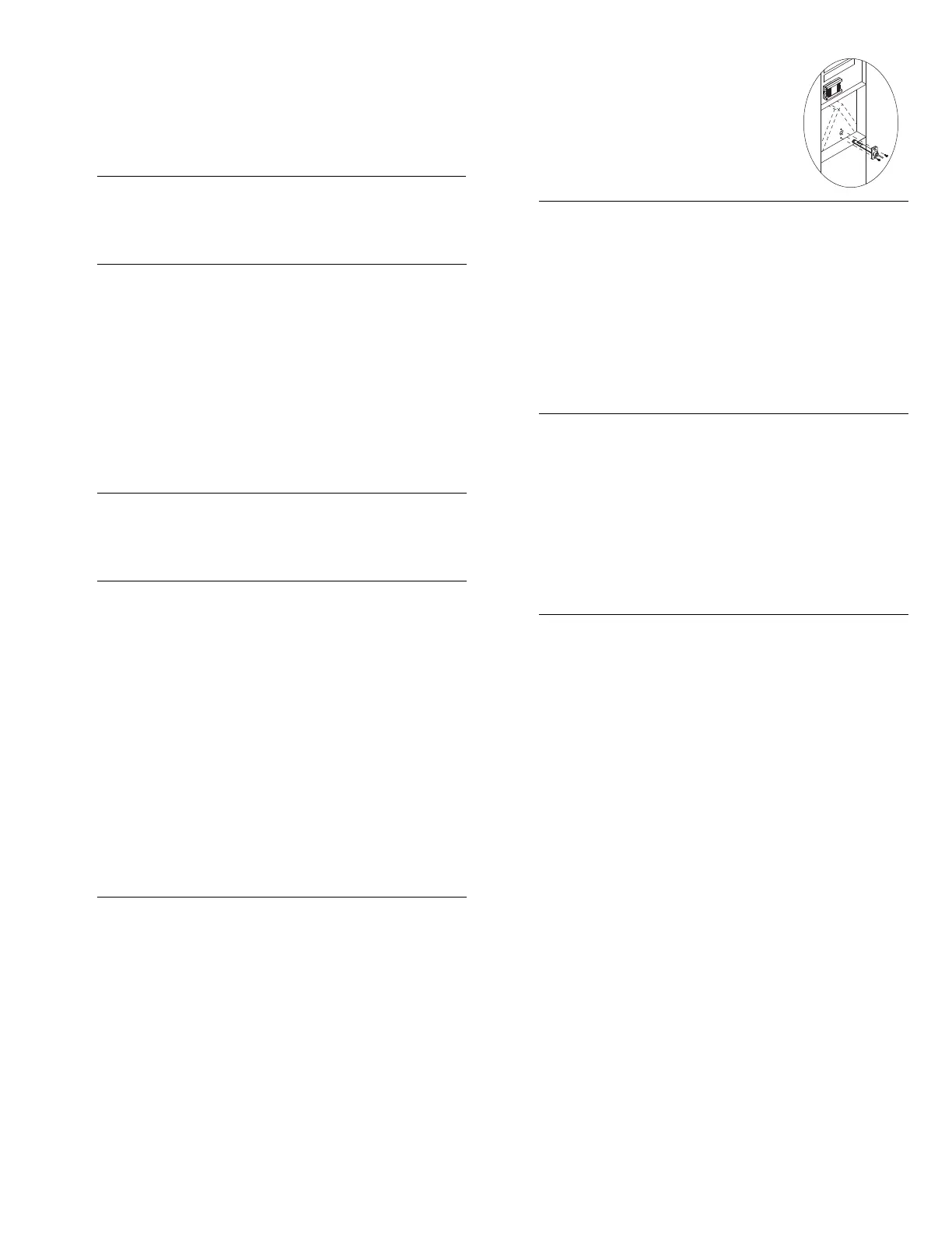
The plenum sensor is required for the following:
• low temperature limit inside the plenum (HVAC only)
• high temperature limit inside the plenum (HVAC only)
• fan limit if gas heating is used (HVAC only)
• high pressure protection during defrost cycle (This protection
is generally needed for add-on installations only. It is not
needed if the heat pump is not connected to the controller
terminal WW.)
Install the sensor on the side of the plenum and
positio
n it such that its aperture faces the air
flow.
Connect the sensor to controller terminals PS
and CS (no polarity). For more information,
refer to the instructions provided with the
sensor.
NOTE: The maximum wiring length is 30 m (100 ft).
NOTE: The dual-energy input can be used only with a heat pump
equipped with auxiliary heat.
The dual-energy input can be connected to the dual-register meter
equipped with a normally open (NO) dry contact. Connect the
controller terminals DE and CC to the meter terminals (yellow and
red wires).
The contact closes when the outdoor temperature drops below the
temperature setting on the meter. When the contact is closed, the
heat pump is disabled and only the auxiliary heat can be used.
To use the unoccupied mode, the controller requires a remote
control device such as Aube’s CT241 telephone controller equipped
with a normally open (NO) dry contact placed between terminals
UN and CC of the controller. The unoccupied mode is activated
when the contact closes. (See user guide.)
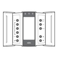
To access the configuration switches, loosen the captive screw
under the console and pull the console from its base.
Backlight (SW1-1)
BL ON: The screen backlight remains on all the time.
AUTO: The screen backlight turns on when a button is pressed
and remains on for 12 seconds.
Access Mode (SW1-2)
INST: Installer mode. Gives access to all configuration
parameters.
NOTE: In installer mode, the short-cycle protection is disabled
and the interstage delay is reduced to 1 minute.
USER: User mode. Gives access to configuration parameter 17
(humidity control) only (see page 8).
Keypad Lock (SW1-3)
I: The keypad is locked. Settings cannot be changed.
O: The keypad is unlocked.
2.3
Heating/Cooling System
2.4
RC845 Relay
2.5
Humidifier
2.6
Outdoor Sensor (AC144-03)
2.7
Plenum Sensor (AC146-410)
2.8
Dual-energy Input
2.9
Unoccupied Mode Input
3. Configuration
3.1
Configuration Switches
 Loading...