TH146-N-2H1C 3/8
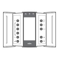
1) Place the console in Installer mode (INST) using the SW1-2
switch on the back of the console.
2) Press the Mode button for 3 seconds to access the
configuration menu (see page 8). The first menu item
(parameter) is displayed.
3) To view another menu item, briefly press the Mode button.
4) To modify a parameter, press either button.
5) To exit the configuration menu, press .
6) Return the console to User mode (USER).
With automatic heating/cooling mode changeover, there’s no need
to adjust the controller at every change of season or weather
condition. The controller switches automatically between heating
mode and cooling mode to maintain the desired temperature. The
mode changeover is triggered as follows:
• The controller switches to cooling mode when the indoor
temperature is higher than the setpoint by more than 1.5°C
(2.5°F) for 15 minutes.
• The controller switches to heating mode when the indoor
temperature is lower than the setpoint by more than 1.5°C
(2.5°F) for 15 minutes.
Balance Points are used to disable the heat pump or the auxiliary
heating when the outdoor temperature is below or above a set
temperature.
• When the outdoor temperature is below the Balance Point
Low (bP L), the heat pump is disabled and only auxiliary
heating can be used (see page 8, item 2).
• When the outdoor temperature is above the Balance Point
High (bP H), the auxiliary heat is disabled and only the heat
pump can be used (see page 8, item 3).
NOTE: Balance Points cannot be used if the AC144-03 outdoor
temperature sensor is not connected to the controller.
The auxiliary heat is activated during defrost except under the
following conditions:
• When the outdoor temperature is above the defrost point
(see page 8, item 4).
NOTE: This condition will not apply if
the AC144-03 outdoor sensor is not connected to the
controller.
• When the plenum temperature is above 40°C (104°F) for
add-on installations only. The auxiliary heat is re-activated
when the plenum temperature drops below 32°C (90°F).
NOTE: This condition will not apply if the AC146-410 plenum
sensor is not connected to the controller.
NOTE: The auxiliary heat’s short-cycle protection is disabled during
defrost.
The controller can be configured for either of the following types of
heat pump installations (see page 8, item 5).
• Add-on Installation: This type of installation is performed
when adding a heat pump to an existing furnace. When the
heat pump is installed, the furnace becomes the auxiliary
heat source. In this type of installation, the indoor coils are
usually installed downstream of the auxiliary heat source.
When the controller is configured for an add-on installation,
the heat pump is disabled during auxiliary heating to prevent
overpressure.
• New Installation: In this type of installation, as there is not
already a furnace, the auxiliary heat source is installed at the
same time as the heat pump. In this type of installation, the
indoor coils are located upstream of the auxiliary heat. When
the controller is configured for a new installation, the heat
pump and the auxiliary heat can operate simultaneously.
Interstage Delay is the time allocated for the temperature to return
to an acceptable value when it deviates too far from the setpoint. If
this time has elapsed, the next heating or cooling stage is activated.
The heating or cooling stage will be deactivated when the
temperature returns to an acceptable value. The Interstage Delay is
fixed at 4 minutes if the controller is configured for an HVAC system
and is user-adjustable if it is configured for a heat pump (see
page 8, item 6).
Low Temperature Limit (LLMT) and High Temperature Limit (HLMT)
are used to keep the plenum from becoming too cold or too hot.
During cooling, if the plenum temperature is lower than LLMT, a
cooling stage is deactivated starting with the one that was last
activated. If, after a while, the temperature is still too low, another
cooling stage is deactivated and so on. Likewise, during heating, if
the plenum temperature is higher than HLMT, a heating stage is
deactivated starting with the one that was last activated. If, after a
while, the temperature is still too high, another heating stage is
deactivated and so on. (see page 8, items 7 and 8.)
WARNING: LLMT and HLMT can be used in parallel with an
UL353-approved device but they do not replace such device.
NOTE: LLMT and HLMT cannot be used if the plenum temperature
sensor is not connected to the controller.
When Smart Fan is enabled (see page 8, item 12), the fan operates
as follows:
• During the unoccupied mode (i.e., when you are away from
home), the fan operates only when heating or cooling is
activated.
• The fan operates continuously the rest of the time.
NOTE: For Smart Fan to work, set the fan to On (see user guide).
3.2
Configuration Menu
4. Principles of Operation
4.1
Automatic Heating/Cooling Changeover
4.2
Balance Points (heat pumps only)
4.3
Heating During Defrost (heat pumps only)
4.4
Types of Heat Pump Installations
4.5
Interstage Delay
4.6
Low and High Temperature Limits
4.7
Smart Fan
 Loading...