INSTALLATION
710-03261-00A 10 MVS SERIES
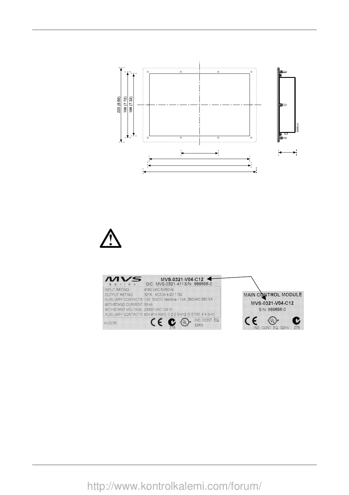
4.2 Mounting Instructions – Controller
The MVS controller can be secured in place with ten M4 nuts, affixed to the bolts
on the back of the controller.
112 (4.41)
300 (11.81)
310 (12.20)
340 (13.39)
54.0 (2.13)
To mount the controller, make a 186 mm x 300 mm cutout at the desired mounting
location. Ensure adequate clearance (54 mm) is available behind the mounting
location.
Drill 5 mm holes to accommodate the bolts on the controller. Fit the controller
through the cutout and tighten the nuts onto the bolts.
NOTE
Before installation, always ensure that you are using the correct controller
for the starter. This can be checked by comparing the serial number on
the back of the controller with the serial number on the front of the power
assembly.
Serial number
http://www.kontrolkalemi.com/forum/