INSTALLATION
MVS SERIES 9 710-03261-00A
Section 4 Installation
4.1 Mounting Instructions – Power Assembly
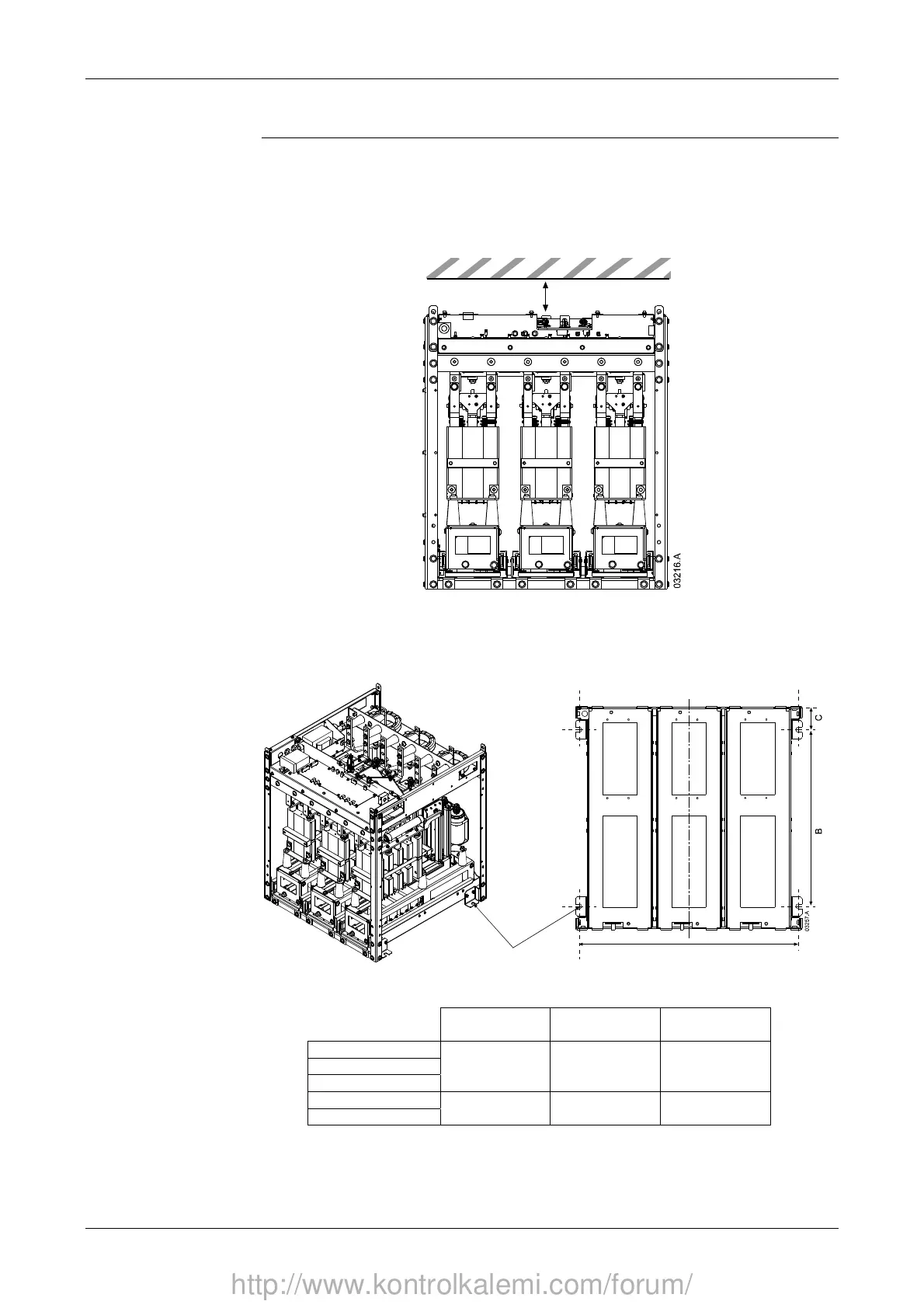
All models in the MVS Series have an IP00 rating and must be installed inside an
enclosure. The power assembly should be installed with 100 mm clearance above
for isolation; no clearance is required below or at the sides.
min 100 mm (3.93 inch)
The MVS power assembly is mounted in place using four M12 bolts. One bolt is
required through each corner at the base of the unit, tightened to a torque of
40 Nm.
Front of Unit
A
To suit M12 mounting bolt
Horizontal Cross-section
A
mm (inch)
B
mm (inch)
C
mm (inch)
MVS-xxxx-V02
MVS-xxxx-V03
MVS-xxxx-V04
636
(25.04)
513
(20.20)
68.5
(2.70)
MVS-xxxx-V06
MVS-xxxx-V07
842
(33.15)
663
(26.10)
68.5
(2.70)
http://www.kontrolkalemi.com/forum/