APPLICATION EXAMPLES
710-03261-00A 18 MVS SERIES
Section 6 Application Examples
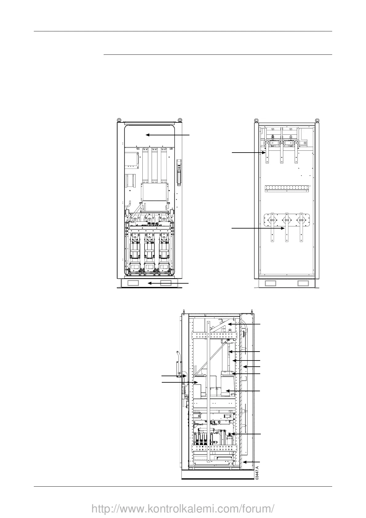
6.1 Installation into a Panel
The MVS panel permits a wide range of installation configurations. Power input
and output can be top or bottom entry and power input can be provided from either
cables or top horizontal bus bars.
The diagrams below illustrate one possible configuration for installation.
Front View
Welded steel plinth
Earth switch viewing window
Rear View
Line bus bars
Motor bus bars
Side View
Interlock mechanism
Fuses
Main contactor
Rear cabling cavity
Power assembly
Bypass contactor
Low voltage trunking
Single phase MV transformer
Three phase MV transformer
Earth / line switch
http://www.kontrolkalemi.com/forum/