– Drill out the holes to 5.0 mm.
– Deburr the holes thoroughly.
– Carefully remove all chips from drilling, e.g. using a work-
shop vacuum cleaner
.
– In order to provide adequate protection against corrosion,
apply the following products with a brush.
◆ Single-component primer filler/surfacer LGF.008.001.42/A3
◆ Two-component vario filler/surfacer, grey LGF.786.004.A3
◆ Audi paint to match the vehicle's colour
◆ Body cavity preserving agent D.330.KD2.A1
– Position and rivet the control unit holder on the insulation
matting.
– Insert the control unit on the retrofit wiring harness, making
sure it engages.
– Screw the control unit to the holder.
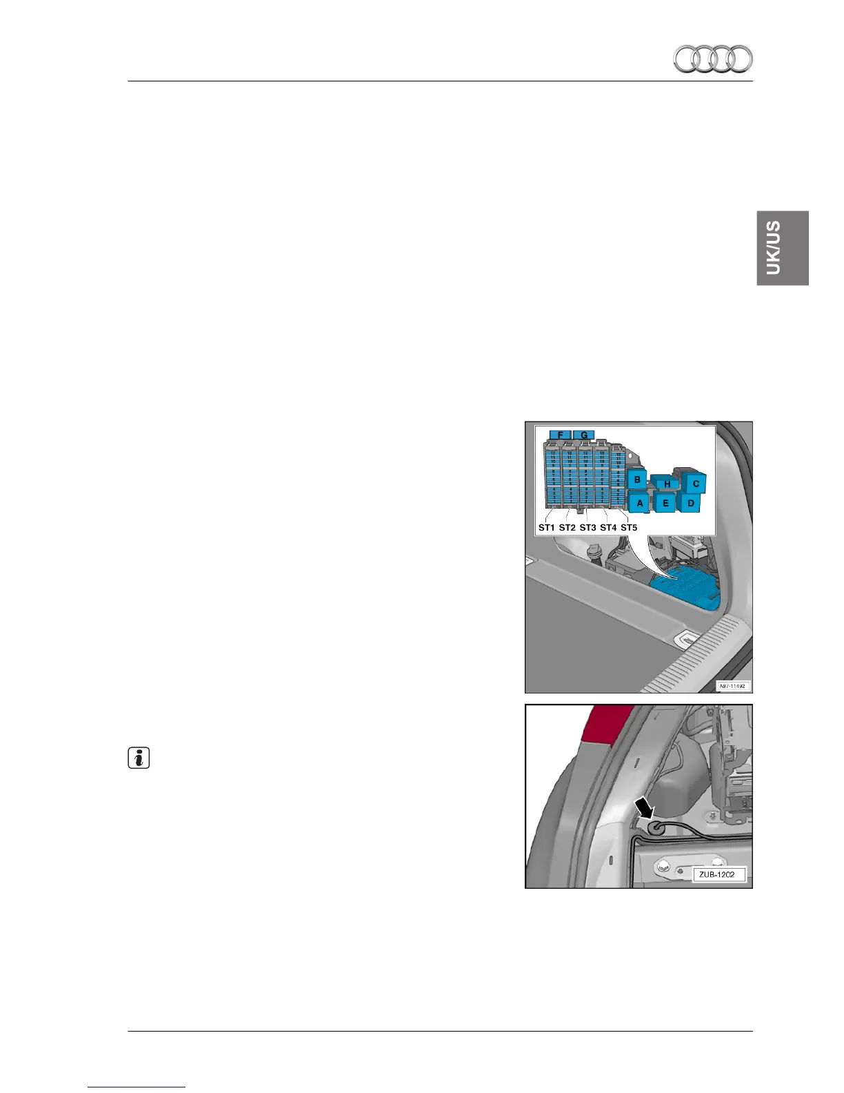
– Lay the retrofit wiring harness along the standard wiring har-
ness to the relay and fuse carrier F -SF-. If the appropriate
equipment is in place, use the cable ties with clip provided to
secure the retrofit wiring harness to the rear panel.
– Lay the connector for the actuators to the corresponding
wire grommets -arrow- .
Note
The clearance for the actuators is created by mounting the ac-
tuators ⇒ “Assembling the exhaust system: 4-cylinder
TDI” on
page 9 and/or ⇒ “Assembling the exhaust system: 6-cylinder
TDI” on page 13.
Installation instructions - Audi A4/A5 (B8 series) 2008 ▶
Edition 1
1/2012
3 Sequence of operations
5