Protected by copyright. Copying for private or commercial purposes, in part or in whole, is not
permitted unless authorised by AUDI AG. AUDI AG does not guarantee or accept any liability
with respect to the correctness of information in this document. Copyright by AUDI AG.
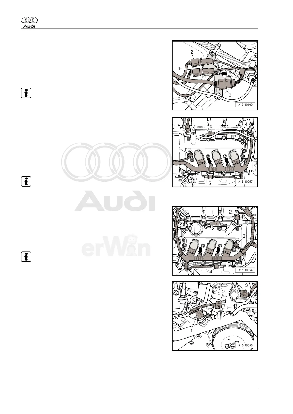
Component Location of Electrical Connectors on Left Rear of En‐
gine
1 - Green; to Knock Sensor (KS) 1 -G61-
2 - Grey; to Knock sensor (KS) 2 -G66-
3 - To cylinder bank 2 fuel injectors and to fuel pressure sensor
-G247-
Note
-Arrow- indicates ground (GND) point
Component Location of Sensor and Valve for Camshaft Adjust‐
ment, Bank 1
1 - Camshaft adjustment valve 1 (exhaust) -N318-
2 - Camshaft adjustment valve 1 -N205-
3 - Camshaft Position (CMP) sensor -G40-
4 - Intake manifold runner position sensor -G336-
5 - Camshaft Position (CMP) sensor 3 -G300-
Note
Ignore -arrows-.
Location of Sensor and Valve for Camshaft Adjustment, Bank 2
1 - Camshaft Position (CMP) sensor 2 -G163-
2 - Camshaft adjustment valve 2 -N208-
3 - Camshaft adjustment valve 2 (exhaust) -N319-
4 - Camshaft Position (CMP) sensor 4 -G301-
Note
Ignore -arrows-.
Component Location Front of Engine
1 - Engine Coolant Temperature (ECT) sensor -G62-
2 - Change over valve for intake manifold flap -N239-
3 - Intake Manifold Tuning (IMT) valve position sensor -G513-
Audi A6 2005 ➤
Fuel Injection and Ignition - Edition 03.2008
12 Rep. Gr.24 - Fuel injection system

 Loading...