Protected by copyright. Copying for private or commercial purposes, in part or in whole, is not
permitted unless authorised by AUDI AG. AUDI AG does not guarantee or accept any liability
with respect to the correctness of information in this document. Copyright by AUDI AG.
2 Description and Operation
⇒ “2.1 Fuel Injection System Component Location”, page 6
⇒ “2.2 Air Filter Assembly Overview”, page 15
⇒ “2.3 Upper Intake Manifold Assembly Overview”, page 16
⇒ “2.4 Lower Intake Manifold Assembly Overview”, page 18
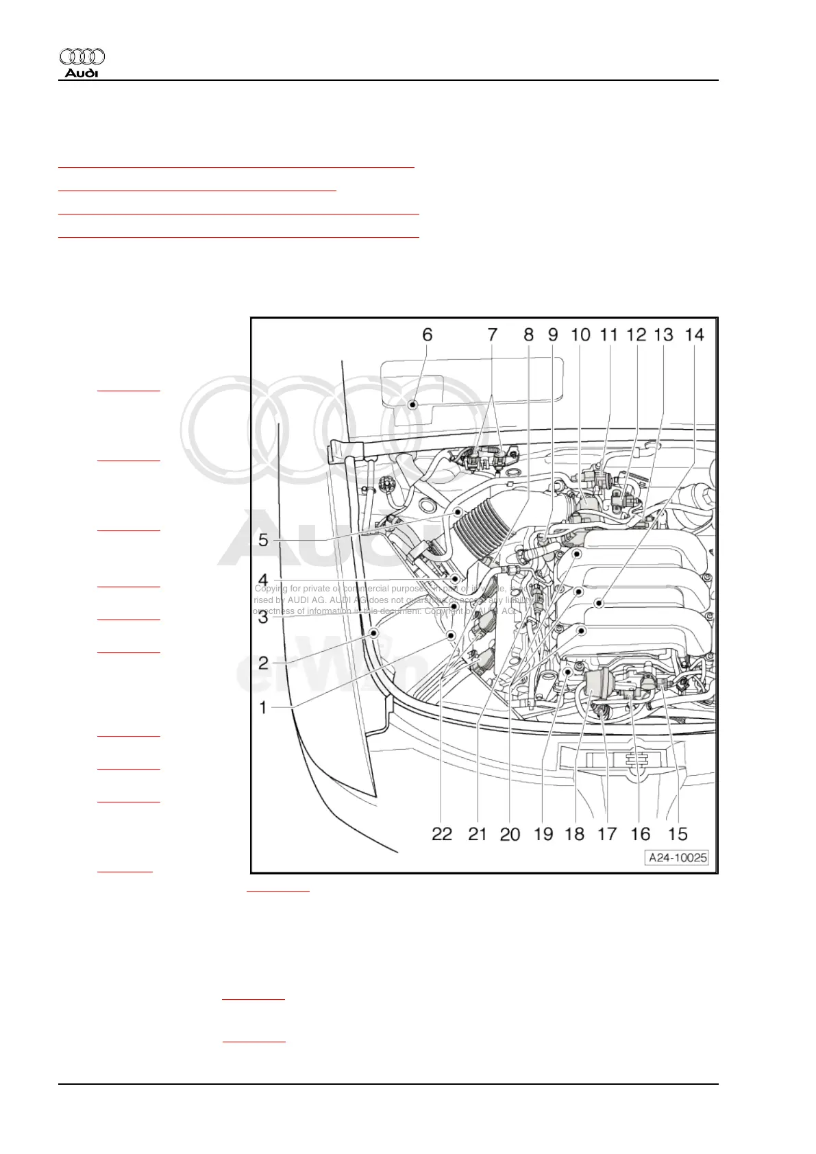
2.1 Fuel Injection System Component Location
Engine Compartment, Right
1 - Right electro-hydraulic en‐
gine mount solenoid valve -
N145-
❑ Component location
⇒ page 13
2 - Intake air switch-over valve
-N335-
❑ Component location
⇒ page 14
3 - Camshaft Position (CMP)
sensor 3 -G300-
❑ Component location
⇒ page 12
4 - Oxygen sensor -G39-
❑ Component location
⇒ page 11
❑ Connector location
⇒ page 10
❑ Removing and installing
⇒ page 44 .
5 - Oxygen Sensor (O2S) be‐
hind Three Way Catalytic Con‐
verter (TWC) -G130-
❑ Component location
⇒ page 11
❑ Connector location
⇒ page 10
❑ Removing and installing
⇒ page 47 .
6 - SIMOS control module -
J361-
❑ Component location
⇒ page 9
❑ Removing and installing ⇒ page 41 .
❑ After replacement, adapt throttle valve control module in operating mode “Guided Fault-Finding” in
“Adapting throttle valve control module”
❑ After replacement on vehicles with automatic transmissions, also perform kick-down adaptation in op‐
erating mode “Guided Fault-Finding” in “Kick-down adaptation”
7 - Right holder for connectors
❑ Connector locations ⇒ page 10
8 - Camshaft adjustment valve 1 (exhaust) -N318-
❑ Component location ⇒ page 12
Audi A6 2005 ➤
Fuel Injection and Ignition - Edition 03.2008
6 Rep. Gr.24 - Fuel injection system

 Loading...