Do you have a question about the Audio enhancement K-SRC14 and is the answer not in the manual?
Button to put the receiver into register mode to pair with a microphone.
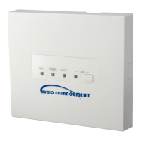
LED indicating power status and unit's ability to receive signals.
LEDs indicating signal reception from microphones.
LED indicating audio link status with WAP or system error.
Terminals for E1/E2 signals, acknowledge, paging mute, RS-232C, and alert button.
Connector for connecting to an amplifier using CAT5 or CAT5e cable.
Unbalanced audio output connector, can mix MIC1/MIC2 with LINE IN.
Stereo line level input connector for external audio sources.
Two sets of switches to configure unit settings, updated on power on.
Cover for ceiling and wall mounting installation access.
Procedure to register the K-STD14 Teacher Microphone with the receiver.
Procedure to register the K-SHH14 Student Microphone with the receiver.
Procedure to pair a third microphone to the receiver.
Lowers LINE IN audio level when microphone audio is present.
Mutes MIC1, MIC2, and mixing output via PAGE MUTE terminal.
Provides operation sound from MIX OUT connector based on volume button.
Mixes MIC1 and MIC2 signals with the mixing out.
Allows external control of unit volume via K-STD14 or RS-232C.
Provides 10dB attenuation for the mixing output.
Reduces feedback loop generated by microphone and speaker proximity.
Control signals for E1/E2 output via K-STD14 microphone.
Receives acknowledge signals responding to E2 output.
Three LEDs indicating operating states and signal reception.
LED indicating link status, pairing mode, or system errors.
Table detailing AP Group ID settings using DIP switch 2 bits.
Connecting audio output from external devices to the LINE IN connector.
Connecting the unit to an amplifier via LAN cable.
Connecting audio input from network cameras or similar to AUDIO OUT.
Instructions for wiring the detachable Euroblock connectors.
Connecting external devices to E1 CNT and E2 CNT terminals.
Connecting external devices to specific control terminals.
Connecting the unit for serial communication with external devices.
General steps for installing the receiver unit.
Specific instructions for mounting the receiver in a ceiling panel.
Specific instructions for mounting the receiver on a wall.
Introduction to serial command usage for remote control.
Describes the standard format for serial commands.
Illustrates command sequences for setting, query, and notification.
Comprehensive list of available serial commands and their parameters.
Solutions for issues where the unit does not receive signals.
Solutions for when no audio output is produced by the unit.
Solutions for intermittent audio or feedback issues.
Troubleshooting for LINK indicator red (WAP/System Error) or yellow (Receiver Trouble).
Solutions for when the receiver repeatedly reboots.
General power, dimensions, mass, and finish details.
Radio standard, frequency range, and coverage details.
Signal-to-noise ratio, frequency response, and connector specifications.
Electrical specifications for control terminals like E1 CNT, E2 ACK, RS-232C.
Interface details for amplifier connection.
Details on volume control functionality.
| Brand | Audio enhancement |
|---|---|
| Model | K-SRC14 |
| Category | Receiver |
| Language | English |