Getting Started Guide
32 APx511 B Series Hearing Instrument Analyzer: Getting Started Guide
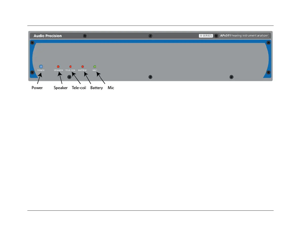
Front Panel Indicators
There are 5 LED indicators on the B Series APx511 front
panel. From left to right, these are:
POWER
This indicator is lit when mains power is applied.
SPEAKER
This indicator is lit when the Speaker output is selected.
TELE-COIL
This indicator is lit when the Telecoil output is selected.
BATTERY
This indicator is lit when the battery reference voltage is on.
MIC
This indicator is lit when power is applied to the micro-
phone input.
Rear Panel Connections
All connections to and from the B Series APx511 are pro-
vided on the rear panel. From left to right these are:
Power Input Module
The mains switch, the mains power input and mains line
fusing are provided in the module. See the Installation chap-
ter earlier in this booklet for detailed information.
Ground connection
This ground lug provides a convenient point to bond the
chassis and technical ground of the APx511 to other equip-
ment as part of a test setup.
Software Options
The APx511 is provided with all the software features and
measurements required for hearing instrument testing. If
you also require PESQ or POLQA testing, optional soft-
ware keys can be purchased. The software keys are con-
nected at the Software Options connector.
 Loading...