Do you have a question about the Audiotec Fischer Match PP 86DSP and is the answer not in the manual?
Instructions for safe and proper installation of MATCH components to prevent damage or injury.
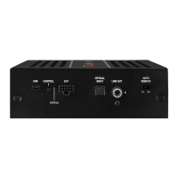
Guidance on connecting the PP 86DSP amplifier to a 12V negative ground vehicle system.
Connector for loudspeakers or passive MATCH PP subwoofer, offering direct connection.
Optical input for digital stereo signals (SPDIF format) for audio signal reception.
Floating-ground low-level outputs for connecting additional power amplifiers.
LED that lights up red when an analog input signal is overdriven.
Control for adjusting the input sensitivity of highlevel inputs.
Highlevel speaker input for channels E and F, connecting directly to speaker outputs.
Connector for the MATCH cable harness, used to connect the amplifier with the car radio.
LED indicating blown internal fuses within the amplifier.
Connector for the +12V power cable to the positive battery terminal.
Connector for the remote cable, used for turning the amplifier on/off.
Connector for the ground cable to the vehicle's chassis or battery negative terminal.
Switch to activate/deactivate the automatic turn-on feature of the amplifier.
Output for turning on/off additional amplifiers connected to the Mono Line Outputs.
Multifunction interface for accessories like remote controls or other MATCH devices.
Input for connecting the PP 86DSP to a PC for configuration via USB.
LED indicating the amplifier's operating mode and chosen setup.
Button to switch between setups or initiate a device reset.
Connects to loudspeakers or passive subwoofers, using four channels for subwoofers.
Digital audio input (SPDIF) with a 12-96 kHz sampling rate, supports stereo only.
Floating-ground low-level outputs for external amplifiers, must use remote output to turn them on.
Indicates overdriven analog inputs; no function for digital or MEC inputs.
Adapts highlevel input sensitivity to signal source, not a volume control.
Highlevel speaker inputs for direct connection to OEM/aftermarket radios, supports 5-11 Volts.
Connects to the MATCH cable harness, do not use other harnesses to connect to car radio.
LED indicating blown internal fuses; replace with identically rated fuses (2 x 25 A).
Connects to the positive battery terminal, requires min. 10 mm² / AWG 8 cable.
Used to turn the PP 86DSP on/off if Auto Remote is not used or if remote signal is preferred.
Connects to a common ground reference point on the vehicle chassis.
Automatically turns amplifier on with highlevel inputs or REM signal; feature can be deactivated.
Outputs remote signals to turn on/off additional amplifiers, activated when DSP booting is complete.
Multifunctional connector for MATCH accessories like remote controls.
Connects to a PC for configuration via USB cable, cannot connect USB storage devices.
Indicates amplifier status: Green for Setup 1, Orange for Setup 2, Red for undervoltage.
Switches between two setup memory positions or erases internal memory.
Combines Class H and D advantages for unsurpassed efficiency and reduced idle losses.
Features ADEP circuit for error protection, avoiding OEM radio failure messages.
Maintains stable internal voltage during engine crank, protects against battery discharge.
Automatically switches to digital input when a signal is detected, can be deactivated.
Reduces power consumption by turning off amplifiers when no input signal is present for 60 seconds.
Diagram and steps for connecting the amplifier to the car radio using provided cables.
Steps to connect the Plug & Play cable harness to the car radio and vehicle harness.
Connects highlevel speaker inputs E and F to OEM/aftermarket radio outputs.
Adjusts input sensitivity for highlevel inputs to match signal source voltage.
Connects digital signal sources via optical input and explains automatic signal detection.
Connects the +12V power cable to the battery positive terminal with an inline fuse.
Connects the remote input to the radio remote output to control amplifier turn-on/off.
Explains how the PP 86DSP turns on automatically and how to deactivate it.
Recommends configuring internal DSP settings via PC-Tool software before first use.
Connects passive subwoofers or loudspeakers to the PP 86DSP outputs.
Used to supply remote signals to additional amplifiers connected to Mono Line Output.
Example of a 5-channel setup using 4 channels for a passive subwoofer.
Example of a 6-channel setup driving two subwoofers with dual voice coils.
Download and install the latest DSP PC-Tool software from the Audiotec Fischer website.
Connect the amplifier to the PC via USB cable, using an active extension if needed.
Power on the amplifier and launch the PC-Tool software after the Status LED turns green.
Configure the PP 86DSP using the PC-Tool software, with additional hints available.
Disconnect all cables from the amplifier before installing an extension card.
Remove the side panel containing the System Connector input by unscrewing Phillips screws.
Remove the bottom plate of the amplifier to access the extension card slot.
Prepare the MATCH Extension Card (MEC) as per its specific manual before installation.
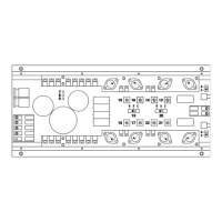
Insert the MEC module into the designated slot marked in the provided picture.
Ensure the MEC module is correctly installed with all pins fully inserted into the socket.
Reassemble the bottom plate and attach the new side panel supplied with the MEC module.
Secure the MEC module to the side panel according to its specific mounting instructions.
Reconnect all previously disconnected cables to the amplifier.
Turn on the amplifier; the MEC module is automatically detected and its LED lights up green.
Configure the installed MEC module using the DSP PC-Tool software.
| DSP | Yes |
|---|---|
| Signal-to-noise ratio | > 98 dB (A-weighted) |
| Damping factor | > 100 |
| Input Voltage | 6 - 17 Volts |
| Amplifier Class | D |
| Frequency Response | 10 Hz - 22, 000 Hz |
| THD | <0.03 % |
| Total Harmonic Distortion | <0.03 % |
| Additional | Bluetooth |
| Dimensions | 46 x 130 x 150 mm / 1.81 x 5.12 x 5.91“ |
| High-Level Input | Yes |
| Low-Level Input | Yes |