128-8971a
6 of 32
6
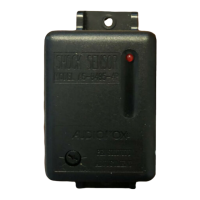
THE OPTIONAL RECEIVER/ANTENNA /PUSHBUTTON/LED ASSEMBLY:
The optional Superheterodyne Receiver Antenna, ADDSS or ADDP1 allows routing from below the dash
board for maximum operating range. Choose a location above the belt line (dashboard) of the vehicle for
best reception. Special considerations must be made for windshield glass as some newer vehicles utilize
a metallic shielded window glass that will inhibit or restrict RF reception. In these vehicles, route the
antenna toward a rear window location for best reception. Secure the antenna with double stick tape
provided. After securing the antenna with tape, we advise also securing a section of the antenna cable to
a fixed support. This will prevent the antenna from dropping down in case the double stick tape is exposed
to extreme heat which may loosen it's gummed surface. Route the 3 connectors toward the control module
and plug the single blue wire's white connector into the mating LED connector on the module, plug the
single gray wire's blue connector into the mating valet/override connector on the module and plug the 3 wire
RF connector into the mating connector of the module, using caution not to pinch the cable as this will
cause poor or no RF reception no LED, or the inability to program the unit.
IMPORTANT!
DO NOT PLUG THE SIX PIN MAIN POWER HARNESS OR THE MULTI PIN INPUT / OUTPUT HARNESS
INTO THE CONTROL MODULE UNTIL ALL CONNECTIONS TO THE VEHICLE HAVE BEEN MADE.
AFTER SELECTING YOUR TARGET WIRES AS DEFINED BELOW, DISCONNECT THE NEGATIVE
BATTERY CABLE FROM THE VEHICLE BATTERY PRIOR TO MAKING ANY CONNECTIONS.
NOTE: Do not remove the fuse holders from this wire harness. Fuses must be used and
located as close as possible to the power source for adequate protection of the vehicle.
WIRING THE 6 PIN MAIN POWER HARNESS: PART # 1123742
NOTE: Do not remove the fuse holders from this wire harness. Fuses must be used and
located as close as possible to the power source for adequate protection of the vehicle.
1 Violet Wire: Accessory Output
Connect this wire to the Accessory wire from the ignition switch. This wire will show + 12 Volts when the
ignition switch is turned to the "ACCESSORY" or "ON" and "RUN" positions, and will show 0 Volts when
the key is turned to the "OFF" and "START" or "CRANK" positions.
2 Blue Wire: Ignition 1 Output
Connect this wire to the ignition 1 wire from the ignition switch. This wire will show +12 Volts when the
ignition key is turned to the "ON" or "RUN" and the "START" or CRANK" positions, and will have 0 Volts
when the key is turned to the "OFF" and "ACCESSORY" positions.
For Diesel Applications, this wire must be connected to the ignition circuit that powers the glow plugs if the
vehicle requires glow plug pre-heating. (See selectable feature Bank 3 #11)
3 Fused Red Wire:
+ 12 Volt Battery 2 Source
Locate the vehicle battery wire(s) at the ignition switch. Verification: These wires will register voltage in all
positions of the ignition switch. Connect the Red wire to the vehicle's battery wire. This wire provides power for the
start relay and the accessory relay.
4 Fused Red/White Wire: + 12 Volt Battery 1 Source
Locate the vehicle battery wire(s) at the ignition switch. Verification: These wires will register voltage in all
positions of the ignition switch. Connect the Red w/White wire to the vehicle's battery wire. This wire provides
power for the control circuit as well as the ignition 1 and ignition 2 relays.
 Loading...