Do you have a question about the Audison LRX 4.300 and is the answer not in the manual?
Safety guidelines for installation, operation, and connection notes.
Critical safety warnings related to installation procedures and potential hazards.
Guidance on selecting appropriate cables for power and signal connections.
Details on power supply cables for different loads and connections.
Recommendations for speaker cables based on terminal blocks and gauge.
Information on available signal cable lengths and types.
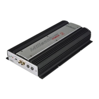
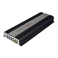
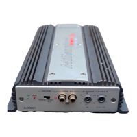
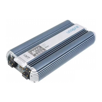
Detailed description of the four-channel car power amplifier's features and performance.
Instructions for physically mounting the amplifier using self-tapping screws.
Diagram and guide for connecting power, speakers, and remote signals.
Procedure for rotating the amplifier's logo for aesthetic placement.
Explanation of input/output panel features including channels A/B and PPS.
Details on remote in/out terminals, VCR connections, fuse, and power terminals.
Wiring diagram for a typical front, rear, and subwoofer system setup.
Wiring diagram for a system with front speakers and a subwoofer.
Wiring diagram for a system with front, rear speakers, and a subwoofer.
Step-by-step guide for safely replacing the amplifier's fuse.
Explanation of amplifier controls like Limit LED, Power LED, and Level adjustments.
Table detailing various amplifier setup configurations and switch settings.
Diagram showing the location and function of controls and configuration switches.
Visual representation of the amplifier's internal signal flow and connections.
Detailed explanation of specific controls like F1 Slope, F1, F2, and Subsonic filter.
Explanation of the safety (red) LED and its indication of protection circuit activation.
Accessing and using the setting panel for configuration and filter adjustments.
Using IN SELECT and X-OVER switches for various system setups.
Description and function of the optional cooling system for demanding conditions.
Procedure for adjusting the subsonic filter frequency using resistors.
Instructions for inserting optional VCA modules for subwoofer volume remote control.
Dimensions and drilling specifications for mounting the amplifier.
Detailed technical specifications including power, filters, inputs, and dimensions.
Information on VCR01K, VCRAK, and VCRDK kits for subwoofer volume control.
| Channels | 4 |
|---|---|
| THD | < 0.05% |
| Damping Factor | > 100 |
| Signal to Noise Ratio | 100 dB |
| Crossover | 12 dB/octave |