Do you have a question about the Audison LRx 5.600 and is the answer not in the manual?
Highlights risks of short circuits and battery damage during installation.
Steps on how to securely mount the amplifier using the provided screws.
Visual guides for connecting speakers, power, and remote signals.
Details on the main fuse and power supply connections.
Detailed steps for opening the cover and replacing the fuse.
Detailed diagram of the controls panel and its configuration switches.
Explanation of the red SAFETY LED and protection circuit status.
Details on using IN SELECT, Ch. SELECT, MODE, and IN SUB switches.
Provides the size for fixing and drilling dimensions for the amplifier.
| Channels | 5 |
|---|---|
| Damping factor | > 200 |
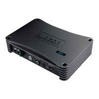
| Dimensions | 300 x 190 x 55 mm |
| Signal-to-Noise Ratio | 100 dB |
| THD | < 0.03% |
| Crossover | 12 dB/octave |