RÉGLAGES SUPÉRIEURS
13
SECTION "A" (A-C)
Canal Gauche (Left) et Droit (Right) de la section A.
A• LEVELS: Réglage de niveau Left - Right des canaux A. La sensibilité est entre 0,15
et 1,5 Volts.
C• MONO IN R: Sélectionne les sorties Left et Right en stéréo (OFF) ou mono (ON).
L'entrée mono IN A - IN B ou IN B pour la configuration à pont (BRIDGE) est Right.
SECTION "B" (B-D-F)
Canal Gauche (Left) et Droit (Right) de la section B.
B• LEVELS: Réglage de niveau Right - Left des canaux B. La sensibilité est entre 0,15 et
1,5 Volts.
D• MONO IN R: Sélectionne les sorties Right et Left en stéréo (OFF) ou mono (ON).
L'entrée mono IN A - IN B ou IN B pour la configuration à pont (BRIDGE) est Right.
F• MIXED MONO (L+R):En ON, il mélange les entrées Left et Right (IN A - IN B ou IN
B), des canaux B en mono. La sorte de connexion des sorties de puissance permet de
choisir la configuration mono deux canaux ou mono en BRIDGE, nécessaire quandil
y a seulement un Subwoofer.
AMBIENT EQUALIZER (E-G)
E• Sélecteur pour mettre en fonction (ON) ou neutraliser (OFF) le filtre AMBIENT
EQUALIZER.
G• Contrôle de niveau qui règle l'intensité d'action du filtre lui-même. Il agit sur les sorties
préamplifiées OUT BY-PASS, sur les sorties de puissance des canaux A et sur les
sorties de puissance des canaux B lorsque les entrées de l'amplificateur sont sélectionnées
en IN A+B (MODE SECTION - H).
MODE ( H )
H• Sélecteur pour l'utilisation de deux ou de quatre entrées.
Position IN A IN B (quatre entrées) Elle permet de piloter les canaux A avec l'entrée
préamplifiée IN A et de piloter les canaux B avec l'entrée préamplifiée IN B.
Position IN A+B (deux entrées) Elle permet de piloter les canaux A et les canaux B avec
l'entrée préamplifiée IN A.
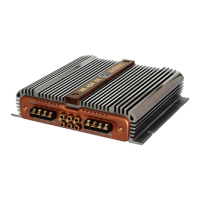
VR 404 XR
CONNECTIONS AND FUNCTIONS
Front Side
OUTPUT
CLAMPS
LO-PASS SPEAKERS
Left and rigth LO-PASS
power outputs.
The available signal is
subjected to the action
of the LO-PASS filter
(which can't be
excluded) includes the
adjustment of the Q
factor.
This varies from 0,7 (cut
slope of the butterworth
LO-PASS filter) to 3 (it
increases the signal by
the set crossover fre-
quency).
The cut-off frequency
can be adjusted in two
ranger from 40 Hz to 800
Hz through special con-
trols put on the upper
part of the amplifier.
IN LO
OUT HI
RCA con-
nectors which
can be used as
signal input or
output.
They can be se-
lected through
the special fun-
ction handled
by the MODE
switch.
Input to drive
the LO-PASS
section of the
device, in this
case the MODE
switch has to be
put on IN LO
position.
HI-PASS ou-
tput, in this case
the MODE
switch has to be
put on OUT HI
position; the
four channels of
the amplifier
are driver by the
IN input.
OUT
BY-PASS
Preamplified
BY-PASS ou-
tputs of the
amplifier.
The available
signal is su-
bjected to the
action of the
AMBIENT
EQUALIZER
filter (which
can be activa-
ted or not)
which handles
the signal
coming from
the IN general
input.
They are for
another am-
plifier, an
electronic
crossover or
any devices
which handle
the musical si-
gnal at a pre-
amplifier
stage.
IN
Left and right inputs
of the amplifier. It
drives directly the
two HI-PASS chan-
nels of the amplifier
and it can also drive
the two LO-PASS
channels when the
MODE button (on
the upper part) is
selected as OUT HI.
In this case the HI-
PASS preamplified
output is available;
it is called IN LO -
OUT HI.
Connections have to
be made from the
preamplified output
of a source, for
example a radio cas-
sette player, a CD
player, an electronic
crossover or any
devices which
handle the musical
signal at a
preamplified stage.
LO-PASS INPUTS
HI-PASS OUTPUTS
HI-PASS
SPEAKERS
Left and rigth
HI-PASS
power outpu-
ts.
The available
signal is su-
bjected to the
action of the
HI-PASS fil-
ter (which
can't be
exclued) and
of the AM-
BIENT
EQUALI-
ZER filter.
The cut off
frequency
can be adju-
sted in two
ranger from
40 Hz to 800
Hz through
special con-
trols put on
the upper
part of the
amplifier.
GENERAL INPUT
BY-PASS
OUTPUTS
OUTPUT CLAMPS
MONO
Power outputs (
L- and
R+
). They have to be
used to connect a mono
subwoofer when the
MIXED MONO BRID-
GE (sum of the channels)
is actived through the
special switches put on
the upper part of the
device.
32
 Loading...