Do you have a question about the Audison VR 404 and is the answer not in the manual?
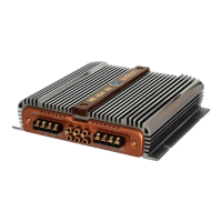
Input for muting the amplifier via an external source, often a mobile phone.
Output to mute other amplifiers in a cascade system.
Input for remote turn-on signal from a source unit.
Output for remote turn-on signal to other amplifiers.
Connection point for the main power supply.
LED indicating the amplifier is active.
LED indicating protection circuit activation.
Controls for Channel A level adjustment and mono output selection.
Controls for Channel B level, mono selection, and input mixing.
Controls for activating and adjusting the Ambient Equalizer.
Switch for selecting input configurations (2 or 4 inputs).
Controls for LO-PASS levels, crossover frequency, range, Q factor, and mixing.
Controls for HI-PASS levels and crossover frequency/range.
Selects amplifier input configuration.
Controls for Ambient Equalizer activation and level.
Speaker outputs for Channel A.
Primary input for Channel A.
Combined input for Channels A and B.
Preamplified output signal bypass.
Speaker outputs for Channel B.
Input for Channel B.
Terminals for mono speaker connection.
Input for muting the amplifier.
Output to mute other amplifiers.
Input for remote turn-on signal.
Output for remote turn-on signal.