10
STEP
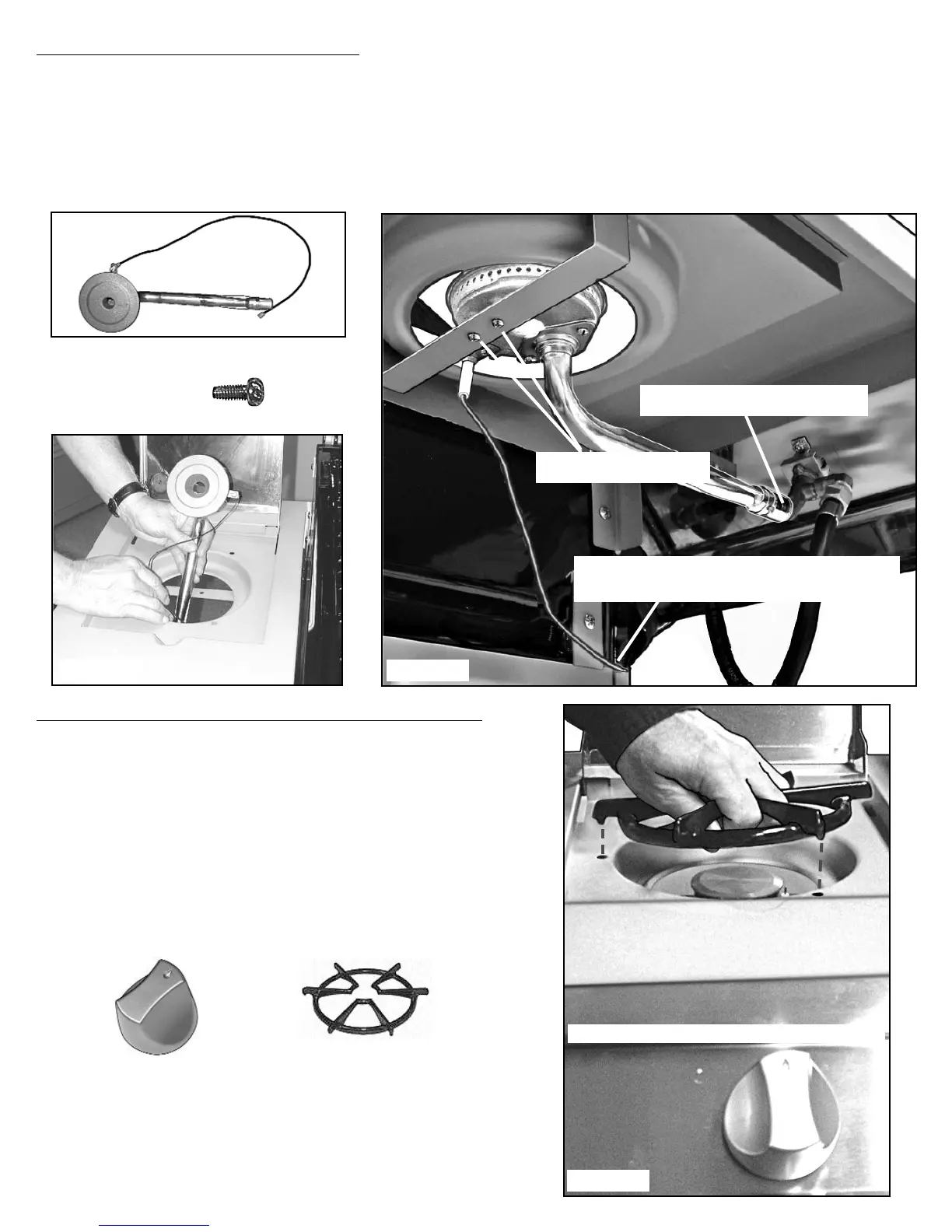
9) SIDE BURNER ASSEMBLY:
Insert the Side Burner (44) and the Electrode Wire through the front of the large hole in the Side
Table. (FIG. 9A) Install the burner tube end over the valve nozzle. (FIG. 9B) Secure the Burner to
the bracket with two M4x8mm Screws (45). (FIG. 9B) Pass the Electrode Wire through the opening
at the top left corner of Side Panel for later connection to Ignition Box. (See also Wiring the
Ignition Box.)
Fig. 9B
Fig. 9A
BURNER TUBE END INSTALLED
OVER VALVE NOZZLE
BURNER SECURED WITH
TWO M4x8mm SCREWS (45)
(44) SIDE BURNER- (46) ELECTRODE WIRE
STEP 10) SIDE BURNER KNOB/GRID ASSEMBLY:
Align the flat keyed hole in the Control Knob (47) with
the keyed stem of the valve. (FIG. 10) Push the Side
Burner Knob onto the Valve stem.
Place the Side Burner Grid (48) onto the Side Burner
Table letting the three protruded ends fall into the three
holes in around the Side Burner.
(48) SIDE BURNER GRID
FIG. 10
(47) CONTROL KNOB
(45) M4 X 8MM
SCREW
PUSH SIDE BURNER KNOB (47) ONTO VALVE STEM
PASS THE ELECTRODE WIRE THROUGH THE
OPENING AT THE TOP LEFT CORNER OF SIDE
PANEL FOR LATER CONNECTION TO IGNITION BOX.