1 Introduction
12.04.2016 Mk8 EGA Set-Up and Trim Guide Page 1
1 INTRODUCTION
1.1 Overview and Benefits
1.1.1 Features and Benefits
The Mk8 Exhaust Gas Analyser (EGA) monitors the emissions in the flue produced from the
burner/boiler system. The EGA can improve combustion, increase efficiency, reduce fuel consumption
and improve safety through its 3 parameter trim function and combustion safety limits.
1. Stand-Alone: When in stand-alone mode, the EGA can be used without a Micro-Modulation
(MM) module to monitor the combustion gases. The MM trim function and the combustion
safety limits are not activated in this stand-alone mode of operation. The emissions levels can
be accessed via the full colour EGA touch screen.
2. With MM: When interfaced with an MM, the EGA can monitor emissions or the 3-parameter
combustion trim and safety limits can be activated. The emissions levels are monitored by the
EGA and the MM makes small adjustments to the air damper to trim the online exhaust gas
data back to the commissioned values. The EGA information is accessible through the full
colour EGA touch screen, the Data Transfer Interface module (DTI), or 6 x 4-20mA signals.
The main benefits of the EGA include the ability to monitor the exhaust gases and bring them to the
safe commissioned levels. Setting the combustion limits on the MM in conjunction with the EGA
prevents unsafe combustion scenarios, reducing the fuel consumed in bad combustion.
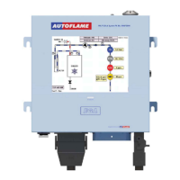
1.1.2 System Operation
The Mk8 EGA samples the combustion gases via the stack mounted sampling probe (purchased
separately from the analyser). The exhaust gases are drawn from the stack by a pump mounted
internally within the analyser. Only the supplied sample tubing should be used between the sampling
probe and analyser. The internal diameter of the sampling tube is 3mm; if a large diameter tubing is
used the sample gas remains resident in the tubing for a longer period. The EGA will then not be able
to respond in time to combustion changes, resulting in incorrect operation of the trim function.
Once the exhaust gases have entered the EGA the chiller block reduces their temperature and dries the
sample to remove the condensation from the gases prior to entering the cells. The condensate
accumulated in the chiller unit is drained every 4 minutes when running, and every 10 minutes when
the EGA is in idle mode, automatically through the drain solenoid.
The exhaust gas is then filtered through the dry filter, which is a fine filter used to remove any dust
particles carried over from the cooling process. If the burner is firing on heavy or dirty oil, an external
particulate filter must be used to remove the excess dirt particles. On leaving the filter, the exhaust gas
pressure is checked again to ensure that a vacuum is maintained prior to entering the pump and on
exiting the pump, the pressure produced by the pump is checked. Both these pressure sensors modulate
the flow rate of the sample into the EGA for consistent operation. Once the exhaust gases have been
conditioned, they are ready for an accurate sampling by the cells. After the gases have been sampled
by all the cells, the remaining sample is pumped out of the EGA from the clear tubing at the bottom of
the EGA casing.
Note: The EGA needs to vent to atmosphere via the drain solenoid on the bottom; this is also where
the EGA performs its air calibrations. Care should be taken to ensure the outlet is not restricted or that
contamination from exhaust gas occurs.
 Loading...