4 Dimensions and Equipment
12.04.2016 Mk8 EGA Set-Up and Trim Guide Page 51
4.3 Sampling Probe
4.3.1 Installation and Maintenance
EGA Sampling Probe Installation
1. Mount the sampling probe at an angle of approximately 45 degrees into the stack.
2. Install a 1.5” BSP socket on the flue or other point that the sampling probe is to be positioned.
3. Mount the main body of the probe as far in as possible; adjustment is made by loosening the
grub screws in the flats of the 1.5” BSP bush supplied on the probe.
4. Keep the thermocouple cable and sample tube away from hot surfaces.
Note: For correct EGA operation the probe must be positioned without air leaks as this
will give incorrect readings on all sensors.
EGA Sampling System Unit Installation
1. Push the sample tube onto the inlet tube. Plug the thermocouple connector into the socket and
tighten the screw.
2. To obtain optimum performance and reliability do not mount the unit in ambient temperatures
above 40°C (104°F) or areas of direct heat radiation. Ensure that the air flow to the intake in
the bottom of the EGA unit is not impeded and the air temperature is less than 40°C (104°F).
3. Do not mount the units where excessive vibration occurs.
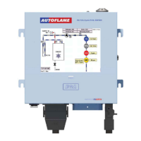
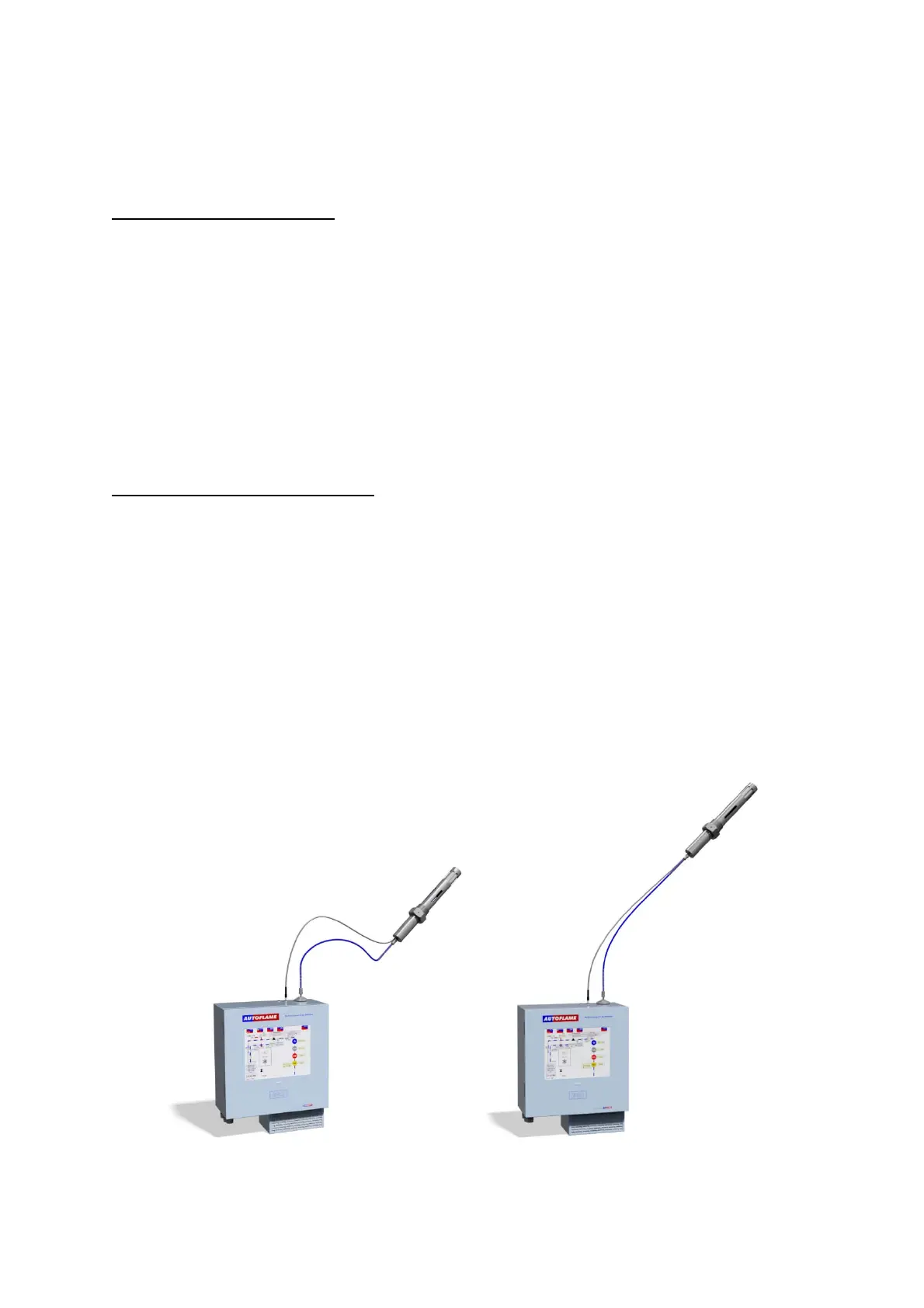
4. Position the sample tube so that the sample slopes down to the EGA unit at all times. The EGA
unit must always be mounted lower than the EGA probe. This helps drain excessive
condensate from the flue gases, which may cause blockages in the sample tube.
Figure 4.3.1.i Incorrect and Correct Installation of an EGA Unit

 Loading...